
1. Product Overview
The HiLetgo ESP32-CAM is a versatile WiFi + Bluetooth dual-mode development board, designed around the ESP32 chip. It functions as a compact, independent system, integrating WiFi, traditional Bluetooth, and BLE Beacon capabilities. Equipped with two high-performance 32-bit LX6 CPUs, it offers a main frequency range of 80MHz to 240MHz. This module is ideal for a wide array of IoT applications, including smart home devices, industrial wireless control, wireless monitoring, and QR identification systems.
This package includes the ESP32-CAM module, an OV2640 2MP camera, and a Micro USB to Serial Port CH340C board for easy programming and connectivity.

Image 1.1: Overview of the HiLetgo ESP32-CAM Camera Module and the accompanying Micro USB to Serial Port CH340C board.
2. Components Included
Your package should contain the following items:
- 2 x ESP32-CAM Module
- 2 x Camera Module OV2640 2MP
- 2 x Micro USB to Serial Port CH340 Board
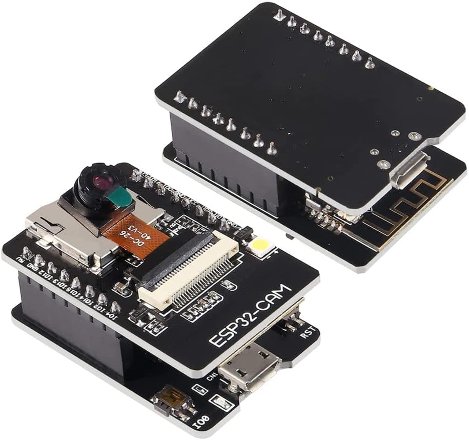
Image 2.1: All components included in the package: ESP32-CAM modules, OV2640 camera modules, and Micro USB to Serial Port CH340 boards.
3. Setup Instructions
Follow these steps to set up your ESP32-CAM module:
- Connect the Camera Module: Carefully connect the OV2640 camera module's FPC cable to the FPC connector on the ESP32-CAM board. Ensure the connection is secure and properly aligned.
- Attach the CH340C Programmer Board: Mount the ESP32-CAM module onto the Micro USB to Serial Port CH340C board. Ensure all pins are correctly aligned and inserted into the corresponding headers on the programmer board.
- Power Supply: Connect the CH340C board to a USB port on your computer. The module requires a stable power supply between 4.75V and 5.25V. Insufficient voltage may lead to unstable operation or programming issues.
- TF Card Insertion: If using, insert a TF (microSD) card into the designated slot on the ESP32-CAM module. Ensure it is inserted in the correct orientation.
- Programming Mode (Important): To flash firmware to the ESP32-CAM, you must temporarily short the pins labeled "IO0" and "GND" on the ESP32-CAM board. While these pins are shorted, press the reset button on the back of the ESP32-CAM module. This puts the board into programming mode, allowing firmware upload via the serial port. After successful upload, remove the short and press reset again to run the new firmware.

Image 3.1: The ESP32-CAM module with the OV2640 camera module properly attached.

Image 3.2: The ESP32-CAM module securely connected to the Micro USB to Serial Port CH340C programmer board.
4. Operating the Module
The ESP32-CAM is designed for various embedded applications. Key operational aspects include:
- Wireless Connectivity: Supports 802.11b/g/n Wi-Fi and Bluetooth 4.2 standards. It can operate in STA (client), AP (access point), or STA+AP working modes.
- Image Upload: Supports direct image upload via Wi-Fi, enabling remote monitoring and data transfer.
- Network Configuration: Features Smart Config and AirKiss One-click distribution network for easy setup.
- Firmware Updates: Supports both serial local upgrade and remote firmware upgrade (FOTA), allowing for easy maintenance and feature enhancements.
- Development: Fully supports secondary development, providing flexibility for custom applications.

Image 4.1: Detailed pinout diagram for the ESP32-CAM module, showing various I/O, power, and communication pins.

Image 4.2: Dimensional drawing of the ESP32-CAM module, providing measurements for integration into projects.
5. Maintenance
To ensure the longevity and optimal performance of your ESP32-CAM module:
- Keep the module clean and free from dust and moisture.
- Avoid exposing the module to extreme temperatures or direct sunlight.
- Handle the camera module and FPC cable with care to prevent damage.
- Ensure proper ventilation if the module is enclosed in a casing during operation.
6. Troubleshooting
If you encounter issues with your ESP32-CAM module, consider the following:
- Module Not Responding/Flashing Issues:
- Ensure the "IO0" and "GND" pins are correctly shorted during the programming process, and the reset button is pressed.
- Verify your power supply is stable and provides 5V. Unstable or low voltage can prevent proper flashing.
- Try a different USB port or USB cable. Some ports may not provide sufficient power or stable data connection.
- Ensure the correct drivers for the CH340C chip are installed on your computer.
- Camera Not Working/Poor Image Quality:
- Check that the FPC cable of the OV2640 camera is securely and correctly inserted into the connector on the ESP32-CAM board.
- Verify that the camera is enabled and configured correctly in your firmware code.
- Unstable Operation/Frequent Crashes:
- Ensure adequate power supply. Fluctuations can cause instability.
- Check for short circuits or loose connections on the board.
- Consider re-flashing the firmware to ensure a clean installation.
7. Specifications
| Feature | Specification |
|---|---|
| Model Name | ESP32-CAM |
| CPU | Low-power dual-core 32-bit CPU (up to 240MHz, 600 DMIPS) |
| Wi-Fi Standard | 802.11b/g/n |
| Bluetooth Standard | Bluetooth 4.2 (BT/BLE SoC module) |
| SRAM | Built-in 520 KB |
| PSRAM | External 4M |
| Supported Interfaces | UART/SPI/I2C/PWM/ADC/DAC |
| Camera Support | OV2640 and OV7670 (with built-in flash) |
| TF Card Support | Yes |
| Product Dimensions | 1.57 x 1.06 x 0.08 inches |
| Item Weight | 0.704 ounces |
8. Warranty and Support
For specific warranty information regarding your HiLetgo ESP32-CAM Camera Module, please refer to the documentation provided at the time of purchase or contact HiLetgo directly. Warranty terms may vary based on region and retailer.
For technical support, troubleshooting assistance, or any product-related inquiries, please contact the manufacturer:
- Manufacturer: HiLetgo
- Website: www.hiletgo.com
- Email: support@hiletgo.com

Image 8.1: Product packaging displaying HiLetgo's website and support email for customer assistance.