1. Product Overview
The ANENG Q1 is a 9999 counts True RMS digital multimeter designed for accurate measurement of various electrical parameters. It features an EBTN black screen with a large, backlit LCD for clear readability in diverse lighting conditions. This device supports both automatic and manual ranging, offering flexibility for different measurement needs. It includes an analog bar graph display for quick visual indication of readings.
Key Features:
- True RMS Measurement: Provides accurate readings for non-sinusoidal waveforms.
- NCV (Non-Contact Voltage) Detection: For safe identification of live wires without direct contact.
- Auto/Manual Ranging: User-selectable measurement range for convenience and precision.
- Analog Bar Graph: Visual representation of measurement trends.
- Large Backlit LCD: Enhanced visibility in low-light environments.
- Overload Protection: Ensures safety across all measurement ranges.
- Low Battery Indication: Alerts when battery replacement is needed.
- Data Hold Function: Freezes the displayed reading for easy recording.
- Auto Power Off: Conserves battery life.
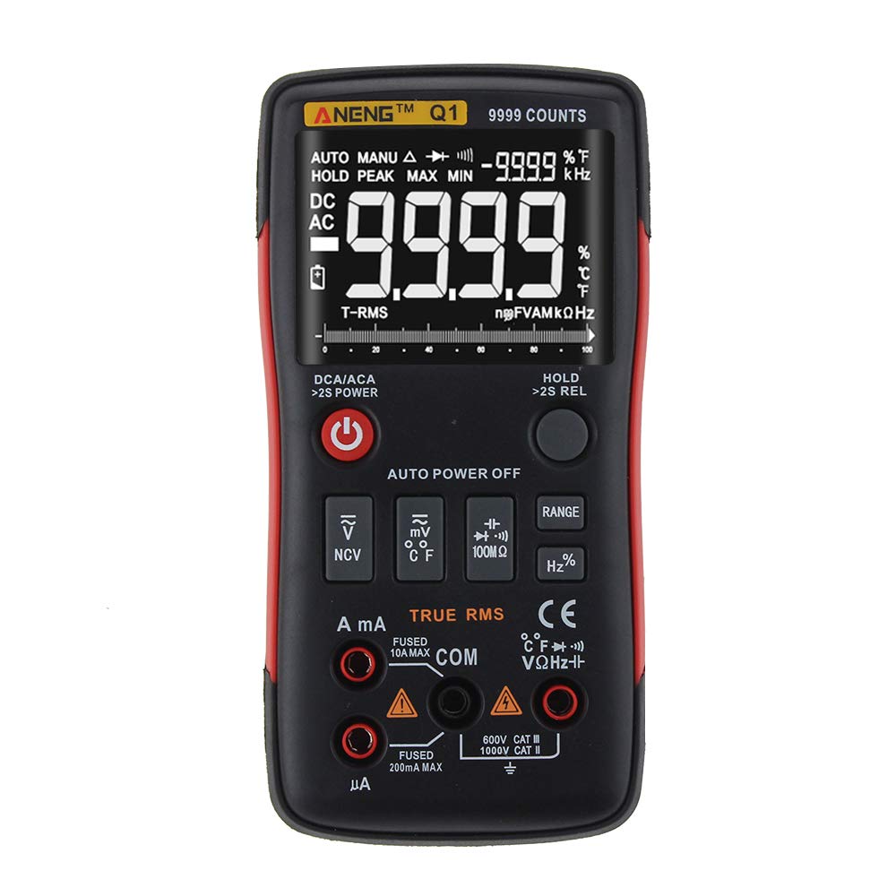
Figure 1: ANENG Q1 Digital Multimeter with its display and function buttons.
2. Safety Information
Always observe basic safety precautions when using this multimeter to prevent personal injury or damage to the device. Read and understand all safety information before operation.
- Do not exceed the maximum input values for any function.
- Use caution when working with voltages above 30V AC RMS, 42V peak, or 60V DC. These voltages pose a shock hazard.
- Before measuring current, ensure the circuit is de-energized and the multimeter is connected in series.
- Always disconnect test leads from the circuit before changing functions.
- Inspect test leads for damaged insulation or exposed metal before use. Replace if damaged.
- Do not operate the multimeter if the battery cover is not properly closed.
- Replace batteries immediately when the low battery indicator appears to ensure accurate readings.
- Adhere to local and national safety codes.
3. Setup
3.1 Battery Installation
- Ensure the multimeter is powered off.
- Locate the battery compartment on the back of the device.
- Unscrew the battery compartment cover and remove it.
- Insert two 1.5V AA batteries, observing the correct polarity (+/-).
- Replace the battery cover and secure it with the screw.
3.2 Connecting Test Leads
The multimeter comes with a set of test leads. Always connect the black lead to the 'COM' (Common) jack. Connect the red lead to the appropriate input jack based on the measurement function:
- VΩHz+ jack for Voltage, Resistance, Frequency, Capacitance, Diode, and Continuity measurements.
- mA jack for current measurements up to 999.9mA.
- 10A jack for current measurements up to 10A.

Figure 2: Included test leads and probes.

Figure 3: Complete ANENG Q1 Multimeter kit with accessories.
4. Operating Instructions
The ANENG Q1 multimeter offers both automatic and manual ranging. Press the 'RANGE' button to switch between auto and manual modes. In manual mode, press 'RANGE' repeatedly to cycle through available ranges.
4.1 Power On/Off
Press the red power button to turn the multimeter on or off. The device features an auto power-off function to conserve battery life after a period of inactivity.
4.2 Measuring AC/DC Voltage (V)
- Connect the black test lead to the 'COM' jack and the red test lead to the 'VΩHz+' jack.
- Select the voltage measurement function (AC V or DC V) using the function button.
- Connect the test probes in parallel across the circuit or component to be measured.
- Read the voltage value on the display.
4.3 Measuring AC/DC Current (A/mA/µA)
- Important: Ensure the circuit is de-energized before connecting the multimeter for current measurement.
- Connect the black test lead to the 'COM' jack. Connect the red test lead to the 'mA' jack for currents up to 999.9mA, or to the '10A' jack for currents up to 10A.
- Select the current measurement function (AC A or DC A).
- Open the circuit and connect the multimeter in series with the load.
- Re-energize the circuit and read the current value on the display.
4.4 Measuring Resistance (Ω)
- Connect the black test lead to 'COM' and the red test lead to 'VΩHz+'.
- Select the resistance measurement function.
- Ensure the circuit or component is de-energized before measuring resistance.
- Connect the test probes across the component.
- Read the resistance value on the display.
4.5 Measuring Capacitance (F)
- Connect the black test lead to 'COM' and the red test lead to 'VΩHz+'.
- Select the capacitance measurement function.
- Ensure the capacitor is fully discharged before measurement to prevent damage to the multimeter.
- Connect the test probes across the capacitor terminals.
- Read the capacitance value on the display.
4.6 Measuring Frequency (Hz) and Duty Cycle (%)
- Connect the black test lead to 'COM' and the red test lead to 'VΩHz+'.
- Select the frequency/duty cycle measurement function.
- Connect the test probes across the signal source.
- Read the frequency or duty cycle value on the display.
4.7 Measuring Temperature (°C/°F)
- Connect the temperature probe to the appropriate input jacks (usually 'COM' and 'VΩHz+' or dedicated temperature jacks if available).
- Select the temperature measurement function.
- Place the tip of the temperature probe on or near the object whose temperature is to be measured.
- Read the temperature value on the display.
4.8 Diode Test
- Connect the black test lead to 'COM' and the red test lead to 'VΩHz+'.
- Select the diode test function.
- Connect the red probe to the anode and the black probe to the cathode of the diode.
- The display will show the forward voltage drop. Reverse the probes; an open circuit (OL) indicates a good diode.
4.9 Continuity Test
- Connect the black test lead to 'COM' and the red test lead to 'VΩHz+'.
- Select the continuity test function.
- Connect the test probes across the circuit or component.
- A continuous beep indicates a low resistance path (continuity).
4.10 NCV (Non-Contact Voltage) Detection
- Select the NCV function.
- Bring the top of the multimeter close to the conductor or outlet.
- The device will indicate the presence of AC voltage through an audible alarm and/or visual indicator.
5. Maintenance
5.1 Cleaning
Wipe the case with a damp cloth and mild detergent. Do not use abrasives or solvents. Ensure the device is completely dry before use.
5.2 Storage
When not in use for extended periods, remove the batteries to prevent leakage. Store the multimeter in a cool, dry place, away from direct sunlight and extreme temperatures. The recommended storage conditions are -20°C to 60°C (-4°F to 140°F) with humidity less than 80% RH.
6. Troubleshooting
- No Display: Check battery installation and ensure batteries are not depleted. Replace if necessary.
- Incorrect Readings: Verify that the correct function and range are selected. Ensure test leads are properly connected and not damaged. Check battery level.
- 'OL' (Overload) Display: The measured value exceeds the selected range or the maximum input limit. Switch to a higher range or ensure the input is within the device's specifications.
- No Continuity Beep: Check if the circuit is truly continuous and has very low resistance. Ensure test leads are making good contact.
7. Specifications
7.1 Electrical Specifications

Figure 4: Electrical Specifications - DC and AC Voltage.

Figure 5: Electrical Specifications - DC and AC Current, and Resistance.

Figure 6: Electrical Specifications - Capacitance, Frequency, and Duty Cycle.

Figure 7: Electrical Specifications - Temperature, Diode, Continuity, and NCV.
7.2 General, Mechanical, and Environmental Specifications

Figure 8: General, Mechanical, and Environmental Specifications.
| Parameter | Value |
|---|---|
| Display | 9999 Counts LCD |
| Ranging | Auto/Manual |
| Material | ABS+TPE |
| Update Rate | 3 Times/Second |
| True RMS | Yes |
| Data Hold | Yes |
| Backlight | Yes |
| Low Battery Indication | Yes |
| Auto Power Off | Yes |
| Parameter | Value |
|---|---|
| Dimension | 146*74*34mm |
| Weight | 125g |
| Battery Type | 2 x 1.5V AA Battery (not included) |
| Parameter | Value |
|---|---|
| Operating Temperature | 0~40°C |
| Operating Humidity | <75% RH |
| Storage Temperature | -20~60°C |
| Storage Humidity | <80% RH |
8. Warranty and Support
8.1 Warranty
This ANENG Q1 Digital Multimeter comes with a one-year warranty from the date of purchase, covering manufacturing defects. This warranty does not cover damage caused by misuse, accident, unauthorized modification, or normal wear and tear. Please retain your proof of purchase for warranty claims.
8.2 Customer Support
For technical assistance, troubleshooting, or warranty inquiries, please contact the retailer or manufacturer's customer service. Refer to your purchase documentation for specific contact details.


