DAOKI DR-US-007
USB Programmer CH341A Series Burner Chip User Manual
Model: DR-US-007 | Brand: DAOKI
1. Introduction
This manual provides comprehensive instructions for the DAOKI CH341A USB Programmer, designed for reading, writing, erasing, and calibrating various EEPROM and SPI Flash chips. It is an essential tool for electronics enthusiasts, technicians, and professionals working with BIOS, firmware, and embedded systems.
Key Features:
- Support for 24 Series EEPROM and 25 Series SPI FLASH chips.
- USB to TTL functionality.
- Support for downloading STC series procedures for single-chip microcontrollers.
- SPI PIN for multi-function extension.
- Automatic identification of 25 series chip models.
- R&W (Read/Write) indicators for operational status.
- Integrated AMS1117 Regulator chip for stable power.
- 12M Crystal Oscillator for precise timing.
- New Original CH341A Chip for reliable performance.
- 500mA Self-Recovery Fuse for circuit protection.
- Selectable 3.3V/5V output voltage.

Figure 1: Overview of the CH341A USB Programmer kit, including the main programmer unit, SOP8 test clip, and adapter boards.
2. Package Contents
Verify that all items listed below are included in your package:
- 1 x CH341A USB Programmer
- 1 x SOP8 SOIC8 Test Clip
- 1 x SOP8 SOP16 to 8 Pin Universal Adapter
- 2 x 4 Pin header

Figure 2: The CH341A USB Programmer shown with its various adapter boards and pin headers, ready for different chip types.
3. Setup Guide
3.1 Driver Installation
Before connecting the CH341A programmer to your computer, it is crucial to install the necessary drivers. The CH341A chip requires specific drivers for proper communication with your operating system (Windows, Linux, etc.).
- Obtain Drivers: Drivers are typically provided on a mini-CD with the programmer or can be downloaded from reputable online sources. Search for "CH341A driver" or "CH341SER.EXE".
- Install Drivers: Run the driver installer. Follow the on-screen prompts to complete the installation. Administrator privileges may be required.
- Verify Installation: After installation, connect the CH341A programmer to a USB port on your computer. Open Device Manager (on Windows) and check under "Ports (COM & LPT)" or "Universal Serial Bus controllers" for "USB-SERIAL CH341A" or similar entry. If it appears without a warning sign, the drivers are correctly installed.
3.2 Software Installation
Several software applications are available for interacting with the CH341A programmer. Popular choices include "CH341A Programmer" (various versions like 1.18, 1.29, 1.34) or "ASProgrammer".
- Download Software: Download the programming software from a trusted source.
- Extract/Install: Most software comes as a portable executable or a simple archive. Extract it to a convenient location.
- Launch Software: Run the executable file (e.g., CH341AProgrammer.exe or ASProgrammer.exe).
Note: Some users report issues with certain software versions or potential malware from untrusted sources. Always download from official or highly reputable communities. ASProgrammer is often recommended for its reliability.
4. Operating Instructions
This section outlines the general procedure for reading, erasing, and writing to supported chips using the CH341A programmer.
4.1 Chip Connection
Properly connecting the chip to the programmer is critical. Incorrect orientation or poor contact can lead to read/write errors or damage to the chip/programmer.
- For DIP/SOP8/SOP16 Chips:
- Using the ZIF Socket: For DIP chips, insert the chip into the ZIF (Zero Insertion Force) socket on the CH341A programmer. Ensure Pin 1 of the chip aligns with the indicator on the socket (usually a small arrow or dot). Gently push down the lever to secure the chip.
- Using SOP Adapters: For SOP8 or SOP16 chips, solder the chip onto the appropriate adapter board (SOP8/SOP16 to DIP8). Then, insert the adapter board into the ZIF socket, again ensuring Pin 1 alignment.
- Using the SOP8 Test Clip:
The test clip allows in-circuit programming without desoldering the chip. This is often used for BIOS chips on motherboards.
- Identify Pin 1 on the target chip (usually marked with a dot or small indentation).
- Connect the red line on the test clip cable to Pin 1 of the chip.
- Carefully attach the clip to the chip, ensuring all pins make good contact.
- Connect the other end of the test clip cable to the 2x4 pin header on the CH341A programmer.

Figure 3: Detailed view of the SOP8 test clip, showing the red line indicator for Pin 1 alignment and its connection to the programmer.
Important: When using the test clip for in-circuit programming, it is often necessary to disconnect power from the target device (e.g., motherboard) or even remove the BIOS battery to prevent interference or damage. Some devices may require a 3.3V modification to the programmer for stable operation with certain chips.
4.2 Basic Programming Operations
Once the chip is connected and the software is running, you can perform the following operations:
- Select Chip Type: In the programming software, select the correct chip manufacturer and model from the dropdown lists. Some software can auto-detect 25 series chips.
- Read Chip: Click the "Read" button to read the contents of the chip into the software's buffer. It is highly recommended to save a backup of the original chip content before any write operations.
- Erase Chip: Click the "Erase" button to clear the chip's memory. This is usually required before writing new data.
- Load File: Load the firmware or data file (usually a .bin or .hex file) you wish to write to the chip.
- Write Chip: Click the "Write" button to program the chip with the loaded file.
- Verify Chip: After writing, click the "Verify" button to compare the chip's content with the loaded file, ensuring the write operation was successful.

Figure 4: The CH341A USB Programmer shown in operation, connected to a chip using the SOP8 test clip.
5. Maintenance
To ensure the longevity and reliable operation of your CH341A USB Programmer, follow these maintenance guidelines:
- Storage: Store the programmer and its accessories in a dry, dust-free environment, away from direct sunlight and extreme temperatures.
- Cleaning: Use a soft, dry cloth to clean the programmer. Avoid using liquid cleaners or solvents. For stubborn dust in the ZIF socket, use compressed air.
- Handling: Handle the programmer and chips with care. Avoid bending pins or applying excessive force.
- USB Port: Always insert and remove the USB connector gently.
- Test Clip: Inspect the test clip for bent or damaged pins before each use. Ensure the spring mechanism operates smoothly.
6. Troubleshooting
If you encounter issues while using the CH341A USB Programmer, refer to the following common problems and solutions:
- Programmer Not Detected by Computer:
- Ensure drivers are correctly installed (refer to Section 3.1).
- Try a different USB port or a different USB cable.
- Restart your computer.
- Chip Not Detected by Software / Read/Write Errors (All F's or FF's):
- Check Chip Connection: Ensure the chip is correctly inserted into the ZIF socket or the test clip is making firm contact with all pins. Verify Pin 1 alignment.
- Power to Target Device (for test clip): If using the test clip, ensure the target device (e.g., motherboard) is powered off and ideally disconnected from its power source. Some setups may require the target device to be powered on, but this is less common and carries risk.
- Voltage Mismatch: Some chips (especially 3.3V chips) may not program correctly if the programmer is outputting 5V. The CH341A has a 3.3V/5V output selection. Ensure it's set correctly. For some chips, a hardware modification to the programmer for stable 3.3V output might be necessary (as noted in customer reviews).
- Chip Compatibility: Verify that your chip model is supported by the CH341A programmer and the software version you are using. Note that ESMT SST class 25 chips can only be read, not written.
- Software Version: Try a different version of the programming software (e.g., ASProgrammer instead of CH341A Programmer, or vice-versa).
- Bad Chip: The chip itself might be faulty.
- Slow Read/Write Speed:
- Ensure you are using a USB 2.0 or higher port.
- Close other demanding applications on your computer.
7. Specifications
| Feature | Detail |
|---|---|
| Brand | DAOKI |
| Model Name | DR-US-007 |
| Hardware Interface | USB |
| Flash Memory Type | FLASH_MEMORY |
| Item Weight | 0.01 Ounces (approx. 0.28 grams) |
| Package Dimensions | 5.75 x 3.39 x 0.87 inches |
| Country of Origin | China |
| Date First Available | October 11, 2019 |

Figure 5: Dimensional drawing illustrating the physical size of the CH341A programmer and its associated adapter boards.
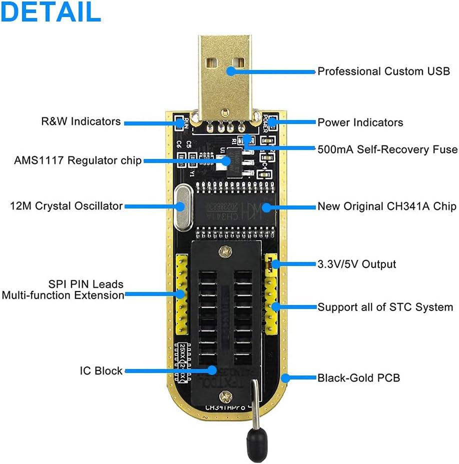
Figure 6: Detailed diagram highlighting key components and features of the CH341A USB Programmer, including indicators, chips, and output pins.
8. Warranty and Support
For warranty information and technical support, please refer to the documentation provided with your purchase or contact the manufacturer directly. Keep your proof of purchase for warranty claims.
Manufacturer: DAOKI
Product Link: https://www.amazon.com/DAOKI-Programmer-CH341A-Burner-EEPROM/dp/B07RV35D4B