1. Introduction
This manual provides essential information for the safe and effective installation, operation, and maintenance of the Eaton XVTL-BP-F-65/20 Frame, Model 174281. This product is designed as a robust frame for industrial electrical enclosures, specifically for XEL systems with nominal dimensions of 650mm (width) by 2000mm (height). Please read this manual thoroughly before proceeding with any installation or maintenance.
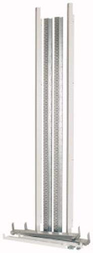
Figure 1: Representative image of an Eaton XVTL-BP-F-65/20 frame component or product label. The actual frame is a larger structural component for electrical enclosures.
2. Safety Information
Always observe the following safety precautions to prevent injury and damage to the equipment:
- Qualified Personnel: Installation and maintenance must only be performed by qualified and authorized personnel familiar with electrical systems and industrial enclosure assembly.
- Power Disconnection: Ensure all power to the installation area is disconnected and locked out before beginning any work on or near the enclosure frame.
- Personal Protective Equipment (PPE): Always wear appropriate PPE, including safety glasses, gloves, and protective footwear.
- Weight and Handling: The frame components can be heavy. Use proper lifting techniques and equipment to avoid injury.
- Environmental Conditions: Ensure the installation environment complies with the product's specified operating conditions.
- Local Regulations: Adhere to all local and national electrical codes and safety regulations.
3. Package Contents
Upon unpacking, verify that all components are present and undamaged. The typical package for the Eaton XVTL-BP-F-65/20 Frame (Model 174281) includes:
- 1x Eaton XVTL-BP-F-65/20 Frame (Model 174281)
- Mounting hardware (e.g., screws, nuts, washers)
- Instruction sheet (this document or similar)
Note: The exact contents may vary based on specific order configurations. Inspect for any shipping damage immediately upon receipt.
4. Setup and Installation
The Eaton XVTL-BP-F-65/20 Frame is designed for integration into an industrial electrical enclosure system. Professional installation is highly recommended.
4.1 Pre-Installation Checks
- Ensure the mounting surface is flat, stable, and capable of supporting the total weight of the assembled enclosure and its contents.
- Verify that the installation area provides adequate clearance for assembly, ventilation, and future maintenance.
- Confirm that all necessary tools and additional components (e.g., enclosure panels, doors, internal mounting plates) are available.
4.2 Frame Assembly (if applicable)
If the frame is supplied in disassembled sections, follow the specific assembly instructions provided with the frame components. Typically, this involves:
- Connecting vertical uprights to horizontal cross-members using the provided fasteners.
- Ensuring all connections are tightened to the manufacturer's specified torque values.
- Verifying the frame is square and level before proceeding.
4.3 Mounting the Frame
The frame can be mounted directly to a floor, plinth, or other structural support. Use appropriate anchoring hardware (not typically included with the frame) suitable for the mounting surface and the expected load.
- Position the frame in the desired location.
- Mark the drilling points for anchors.
- Drill holes and secure the frame using appropriate fasteners.
- Ensure the frame is plumb and level after mounting.
4.4 Integration with Enclosure Components
Once the frame is securely mounted, proceed with attaching enclosure panels, doors, internal mounting plates, and other accessories according to their respective instructions. Ensure proper grounding connections are made for all metallic components.
5. Operating Instructions
The Eaton XVTL-BP-F-65/20 Frame itself is a passive structural component and does not have operational controls. Its function is to provide a stable and secure housing for electrical and electronic equipment within an industrial enclosure. Proper 'operation' of the frame involves ensuring its structural integrity and maintaining the environmental conditions of the enclosure it forms.
- Ensure all enclosure doors and panels are properly closed and secured to maintain the specified IP rating and protect internal components.
- Monitor the internal temperature and humidity of the enclosure if active cooling or heating systems are installed.
- Avoid placing excessive loads on the frame or its attached components beyond their rated capacity.
6. Maintenance
Regular maintenance ensures the longevity and continued safety of the Eaton XVTL-BP-F-65/20 Frame and the enclosure it supports.
6.1 Routine Inspection
Perform visual inspections periodically (e.g., quarterly or annually, depending on the environment):
- Check for any signs of corrosion, rust, or paint damage on the frame.
- Inspect all bolted connections for tightness. Re-tighten if necessary, adhering to specified torque values.
- Verify the integrity of the mounting to the floor or support structure.
- Examine door hinges, latches, and sealing gaskets (if part of the enclosure) for wear or damage.
6.2 Cleaning
Clean the exterior of the frame and enclosure as needed to remove dust, dirt, or other contaminants.
- Use a soft, damp cloth with a mild, non-abrasive cleaning solution.
- Avoid using harsh chemicals or solvents that could damage the finish.
- Ensure the enclosure is dry before re-energizing any internal electrical components.
7. Troubleshooting
This section addresses common issues related to the physical frame structure. For issues related to internal electrical components, refer to their respective manuals.
| Problem | Possible Cause | Solution |
|---|---|---|
| Frame appears unstable or wobbly. | Loose mounting bolts or uneven mounting surface. | Check and re-tighten all mounting bolts. Ensure the mounting surface is level. Add shims if necessary. |
| Difficulty attaching enclosure panels. | Frame not square or level; incorrect panel alignment. | Verify the frame's squareness and levelness. Adjust as needed. Ensure panels are correctly oriented. |
| Visible corrosion or damage. | Exposure to harsh environment; physical impact. | Clean and repair minor damage (e.g., touch-up paint). For significant structural damage, consult Eaton or a qualified professional for assessment and potential replacement. |
8. Specifications
Technical specifications for the Eaton XVTL-BP-F-65/20 Frame, Model 174281:
- Part Number: 174281
- Model Number: 174281
- Nominal Enclosure Dimensions (L x H): 650mm x 2000mm (as per product title)
- Item Dimensions (Packaging/Component): 2 x 3.1 x 1 cm
- Item Weight (Packaging/Component): 10 g
- Number of Items in Package: 1
- Batteries Required: No
- ASIN: B07RS5CF31
- First Available Date: June 20, 2022
Note: The small item dimensions and weight listed are likely for a specific component or the packaging of a smaller part of the overall frame system, not the complete industrial frame itself.
9. Warranty and Support
For information regarding product warranty, technical support, or spare parts, please contact Eaton customer service or your authorized Eaton distributor. Refer to the official Eaton website for the most current contact information and warranty terms applicable to your region.
Eaton Official Website: www.eaton.com


