1. Introduction
This manual provides essential information for the safe and efficient installation, operation, and maintenance of the IFM D100/DY34-A Speed Controller. This device is designed for pulse rate and rotational speed control in industrial applications, operating on 110/120 VAC power. Please read this manual thoroughly before attempting to install or operate the unit.
2. Safety Information
WARNING: Electrical shock hazard. Installation and maintenance should only be performed by qualified personnel.
- Always disconnect power before installing, wiring, or performing maintenance on the device.
- Ensure proper grounding to prevent electrical shock.
- Verify that the supply voltage matches the device's specified voltage (110/120 VAC).
- Do not operate the device in environments exceeding its specified temperature or humidity limits.
- Protect the device from moisture and corrosive substances.
- Refer to local and national electrical codes for all wiring and installation procedures.
3. Product Overview
The IFM D100/DY34-A is a compact speed controller designed for precise monitoring and control of rotational speeds or pulse rates. It features robust construction suitable for industrial environments.
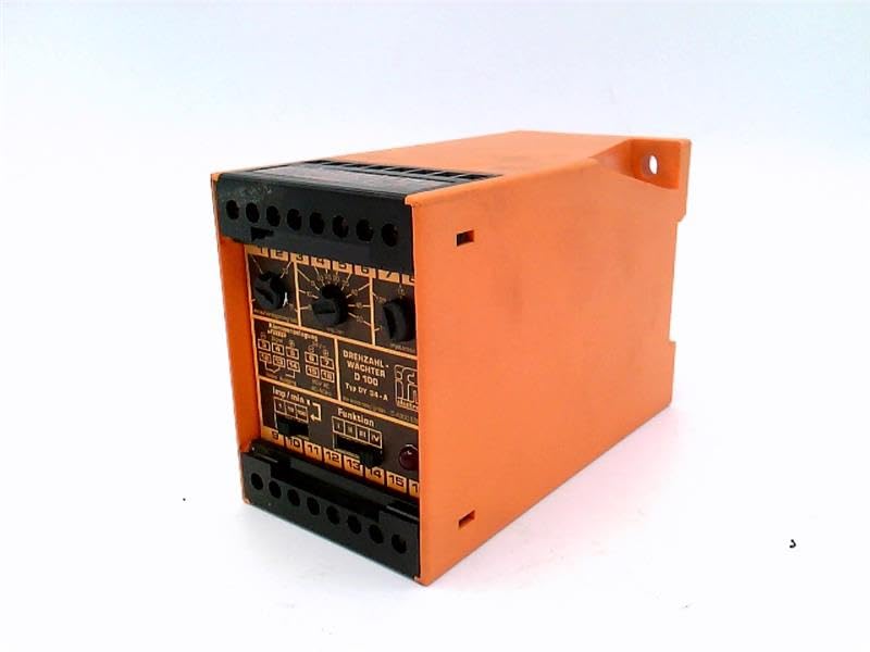
Figure 1: Front view of the IFM D100/DY34-A Speed Controller. The image shows the orange casing, black terminal blocks at the top and bottom, and control dials on the front panel labeled for functions like "DREHZAHL-WACHTER D 100" (Rotational Speed Monitor D 100) and "Funktion" (Function).
Key components include:
- Terminal Blocks: For power input, sensor connections, and output signals.
- Control Dials: Used for setting parameters such as speed thresholds and operating modes.
- Indicator Lights: (If visible/implied) For status indication (e.g., power, output active, error).
4. Setup
4.1 Mounting
The controller is typically mounted on a DIN rail within an electrical enclosure. Ensure adequate ventilation around the unit to prevent overheating.
- Securely attach the unit to a standard DIN rail.
- Ensure sufficient clearance for wiring and heat dissipation.
4.2 Wiring
Refer to the wiring diagram provided on the unit or in the detailed technical documentation for specific connections. General wiring steps include:
- Power Supply: Connect the 110/120 VAC power supply to the designated terminals. Observe correct polarity if applicable.
- Sensor Input: Connect the pulse or rotational speed sensor to the input terminals. Ensure the sensor type (e.g., NPN, PNP) is compatible with the controller.
- Output Connections: Connect the control output(s) to the driven device (e.g., motor contactor, alarm).
- Grounding: Connect the protective earth ground to the designated ground terminal.
CAUTION: Incorrect wiring can damage the device or connected equipment. Double-check all connections before applying power.
5. Operating Instructions
5.1 Initial Power-Up
- After completing all wiring, apply power to the unit.
- Observe any power indicator lights to confirm the unit is receiving power.
5.2 Parameter Setting
The D100/DY34-A features adjustable parameters via its front panel dials. These typically include:
- Set Point (Threshold): Adjust this dial to set the desired speed or pulse rate at which the output will activate or deactivate.
- Hysteresis/Window: (If available) Adjust to prevent rapid switching of the output when the input signal fluctuates around the set point.
- Function Selector: Select the operating mode (e.g., overspeed, underspeed, window function).
Consult the detailed technical manual for precise instructions on calibrating and setting each parameter for your specific application.
5.3 Operation
Once configured, the controller continuously monitors the input signal from the connected sensor. When the monitored speed or pulse rate crosses the set threshold, the corresponding output will change state according to the selected function.
6. Maintenance
The IFM D100/DY34-A Speed Controller is designed for reliable operation with minimal maintenance. However, periodic checks are recommended.
- Cleaning: Keep the unit clean and free from dust and debris. Use a soft, dry cloth for cleaning. Do not use abrasive cleaners or solvents.
- Connections: Periodically inspect wiring connections for tightness and signs of corrosion.
- Environmental Conditions: Ensure the operating environment remains within specified temperature and humidity ranges.
WARNING: Disconnect all power before performing any maintenance or cleaning.
7. Troubleshooting
If the speed controller is not functioning as expected, consider the following common issues:
| Problem | Possible Cause | Solution |
|---|---|---|
| No power indicator light | No power supply; incorrect wiring; blown fuse. | Check power source; verify wiring connections; replace fuse if necessary. |
| Output not activating/deactivating | Incorrect set point; faulty sensor; incorrect function setting; wiring error. | Adjust set point; check sensor operation; verify function selector; inspect output wiring. |
| Erratic readings | Sensor interference; loose connections; faulty sensor. | Check sensor cabling for shielding; tighten connections; test or replace sensor. |
If problems persist after attempting these solutions, contact IFM technical support or a qualified service technician.
8. Specifications
The following specifications are for the IFM D100/DY34-A Speed Controller:
- Model: D100/DY34-A
- Input Voltage: 110/120 VAC
- Function: Pulse Rate/Rotational Speed Control
- Item Weight: 1.84 Pounds
- Manufacturer: EFECTOR (IFM)
- ASIN: B07RRL4XY3
- First Available: February 21, 2025
9. Warranty and Support
For information regarding warranty coverage, technical support, or service, please refer to the official IFM website or contact your local IFM distributor. Keep your purchase receipt and product serial number handy when contacting support.
Note: Specific warranty terms and conditions may vary by region and purchase date.