1. Introduction
This instruction manual provides comprehensive guidance for the installation, operation, and maintenance of the Jectse T80 Intelligent Pressure Level Transmitter Display. This device is designed to accurately measure and display liquid levels using a 4-20mA input signal, offering robust performance in various industrial and environmental applications.
1.1 Key Features
- Wide range of media compatibility, suitable for measuring water, oil, and viscous wastewater.
- Broad temperature compensation range, ensuring stable readings unaffected by foam or fluid deposits, with capability for up to 200 meters depth (with compatible probe).
- Utilizes a diffused silicon sensor for high measurement accuracy and stability.
- Transmitter probe features a full stainless steel sealed structure, silicone oil-filled, ensuring the sensor chip is completely isolated from the medium.
- Equipped with a clear light column display and digital readout for easy monitoring.
- Multiple alarm outputs for enhanced control and safety.
2. Safety Information
Please read and understand all safety instructions before installing or operating the device. Failure to follow these instructions may result in injury or damage to the equipment.
- Electrical Safety: Ensure the power supply is disconnected before any wiring or maintenance. The device operates on AC220V; improper handling can cause electric shock.
- Installation: Installation should only be performed by qualified personnel familiar with electrical systems and industrial instrumentation.
- Environment: Do not expose the device to extreme temperatures, corrosive environments, or excessive vibration beyond its specified operating conditions.
- Maintenance: Only use original or approved replacement parts. Refer to the troubleshooting section for common issues.
3. Package Contents
Verify that all items are present and undamaged upon unpacking:
- 1 x Jectse T80 Intelligent Pressure Level Transmitter Display Unit
- Fixing accessories (e.g., mounting brackets, screws)
4. Product Overview and Components
The Jectse T80 features a front panel with a light column display, a digital PV (Process Value) display, and control buttons. The rear panel provides terminal blocks for power, sensor input, and alarm outputs.
4.1 Front Panel


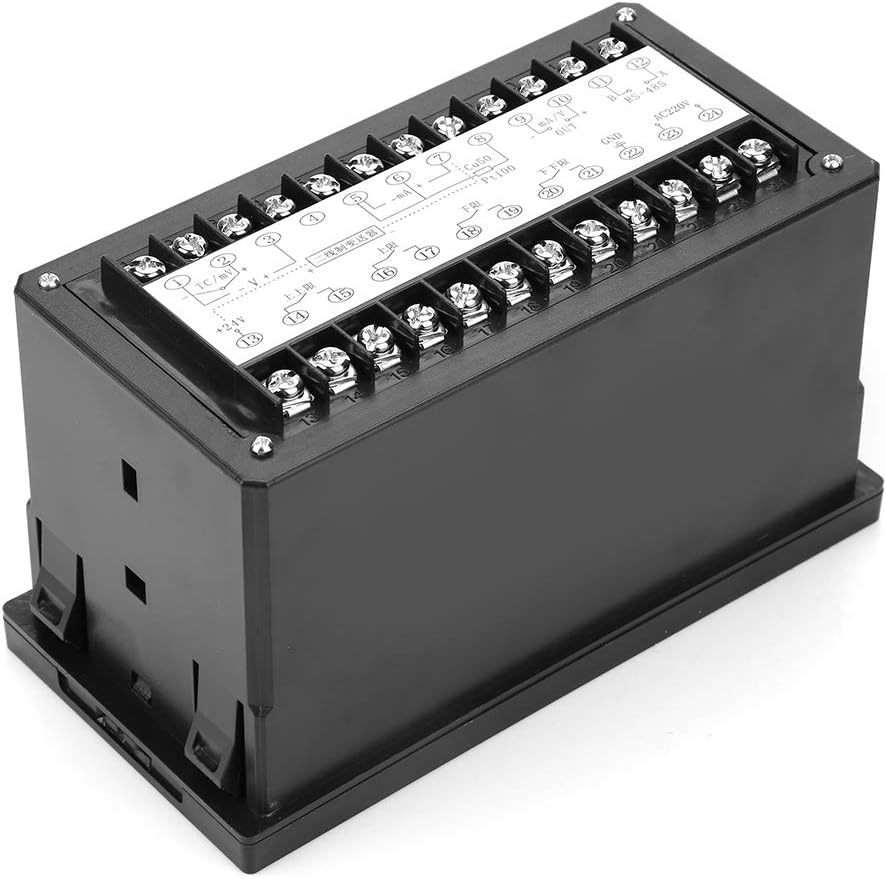
4.2 Rear Panel and Terminals

5. Specifications
| Parameter | Value |
|---|---|
| Model | Jectsesb2puarcx0 (T80) |
| Measurement Error | 1% + 1 digit, 0.5% ± 1 digit, 0.2% ± 1 digit |
| Cold Junction Compensation Error | 0 ~ 50 ℃, ≤ ± 2 ℃ |
| Temperature Coefficient | ≤0.05%/C2 |
| Measurement Range | -1999 ~ 9999, -199 ~ 9999 |
| Alarm Range | Freely adjustable across full scale |
| Relay Output Capacity | 3A/220V, resistive or specified |
| Solid State Relay Output Signal | 15 ± 3V/30mA |
| Working Power | AC220V ~ ± 10% 50Hz |
| Power Consumption | 4 W |
| Working Environment Temperature | 0 ~ 50 ℃ |
| Relative Humidity | 35% ~ 85% Rh |
| Weight | Approx. 321g (11.3 oz) |
| Dimensions (L x W x H) | 20 x 20 x 12 cm |
| Color | Black |
| Mounting Type | Panel Mount |
| Sensor Technology (for compatible probe) | Diffused Silicon Sensor |
| Maximum Measurement Depth (for compatible probe) | 200 Meters |
6. Setup
6.1 Installation
The Jectse T80 is designed for panel mounting. Ensure adequate space for ventilation and access to wiring terminals. Cut a rectangular opening in the panel according to the device's dimensions, then secure the unit using the provided fixing accessories.
6.2 Wiring
Refer to the wiring diagrams below for proper connection of the level transmitter, power supply, and alarm outputs. Always ensure the power supply is disconnected before making any connections.


7. Operation
7.1 Basic Display
Once powered on, the T80 display will show the current process value (PV) on the 4-digit digital display and a visual representation of the level on the 0-100% light column display.
7.2 Button Functions
- SET Button: Used to enter parameter setting mode and confirm selections.
- UP Button: Increases the value of a parameter or navigates through menu options.
- DOWN Button: Decreases the value of a parameter or navigates through menu options.
- MOBILE (Shift) Button: Moves the cursor to select digits during parameter input.
7.3 Parameter Settings
To configure alarm points, measurement range scaling, or other operational parameters, press the SET button to enter the programming mode. Use the UP/DOWN buttons to adjust values and the MOBILE button to select digits. Press SET again to confirm and save changes. Refer to the detailed programming guide (if available from the manufacturer) for specific parameter codes and their functions.
8. Maintenance
Regular maintenance ensures the longevity and accuracy of your Jectse T80 display unit.
- Cleaning: Clean the front panel with a soft, dry cloth. Do not use abrasive cleaners or solvents.
- Connections: Periodically check all electrical connections for tightness and signs of corrosion.
- Calibration: If accuracy issues arise, consult a qualified technician for recalibration.
- Environmental Check: Ensure the operating environment remains within specified temperature and humidity ranges.
9. Troubleshooting
This section addresses common issues you might encounter with the Jectse T80 display.
| Problem | Possible Cause | Solution |
|---|---|---|
| No display/Power off | No power supply; Incorrect wiring; Blown fuse. | Check AC220V power connection; Verify wiring according to diagrams; Replace fuse if necessary. |
| Incorrect readings | Sensor not connected; Sensor faulty; Incorrect parameter settings; Interference. | Check sensor wiring (4-20mA input); Test sensor functionality; Review and adjust scaling parameters; Ensure proper grounding and shielding. |
| Alarms not triggering | Alarm setpoints incorrect; Alarm output wiring faulty; Relay failure. | Verify alarm setpoints in parameter settings; Check alarm output wiring; Test relay functionality. |
| Buttons unresponsive | Device frozen; Physical damage to buttons. | Power cycle the device; If physical damage, contact support for repair. |
10. Warranty and Support
Jectse products are manufactured to high-quality standards. For specific warranty information, please refer to the documentation provided at the time of purchase or contact your vendor. In case of technical issues or support inquiries, please reach out to Jectse customer service or your authorized distributor.
For returns, the product typically has a 31-day return policy from the date of purchase, subject to the seller's terms and conditions.