
NEW Jia Qun K530-6
NEW Jia Qun Lincoln Magnum 100L (K530-6) Compatible MIG Welding Gun Torch User Manual
Model: K530-6 | Brand: NEW Jia Qun
1. Introduction
Thank you for choosing the NEW Jia Qun Lincoln Magnum 100L (K530-6) Compatible MIG Welding Gun Torch. This manual provides essential information for the safe and efficient operation, setup, and maintenance of your welding gun. Please read this manual thoroughly before use and retain it for future reference. This MIG gun is designed for compatibility with Lincoln Magnum 100L (K530-6) systems, offering a 100Amp rating and a 10-foot (3-meter) cable, suitable for 0.024" to 0.031" (0.6mm to 0.8mm) welding wire.

Figure 1: Overview of the NEW Jia Qun Lincoln Magnum 100L Compatible MIG Welding Gun Torch. This image displays the complete welding gun assembly, including the handle, trigger, cable, and connector, ready for use.
2. Safety Information
Welding can be hazardous. Always follow proper safety precautions to prevent injury or damage. This section outlines general safety guidelines. Refer to your welding machine's manual for additional safety instructions.
- Electric Shock Can Kill: Ensure proper grounding. Do not touch live electrical parts. Wear dry welding gloves.
- Fumes and Gases Can Be Hazardous: Work in a well-ventilated area. Use fume extractors if necessary.
- Welding Rays Can Burn Eyes and Skin: Wear a welding helmet with appropriate shade lens. Protect exposed skin with flame-resistant clothing.
- Fire and Explosion Hazard: Keep flammable materials away from the welding area. Have a fire extinguisher readily available.
- Hot Parts Can Cause Severe Burns: Allow welded materials and equipment to cool before handling.
- Read All Instructions: Familiarize yourself with all equipment and safety procedures before beginning any welding operation.
3. Product Overview and Parts Identification
The NEW Jia Qun MIG Welding Gun Torch consists of several key components designed for efficient wire feeding and arc stability.
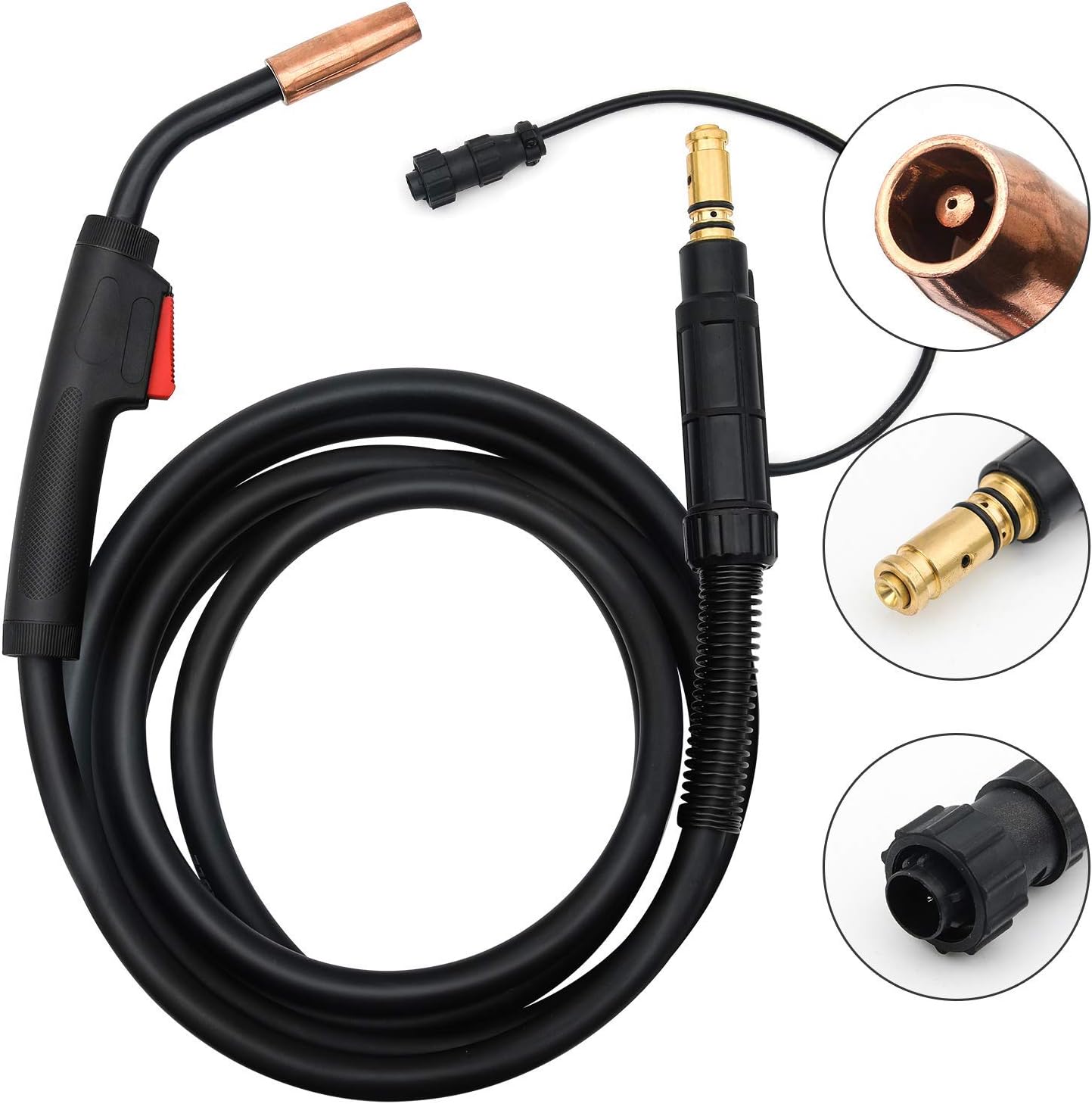
Figure 2: Key components of the MIG Welding Gun. This image highlights the main parts of the welding gun, including the contact tip, gas nozzle, handle with trigger, and the rear connector assembly, providing a visual guide for identification.
- Gun Handle: Ergonomically designed for comfortable grip and reduced fatigue. Features a red trigger for arc initiation.
- Trigger: Activates wire feed and gas flow when pressed.
- Gooseneck/Gun Tube: The curved metal tube that directs the welding wire and gas to the weld puddle. Armored with an electrically insulated metal jacket.
- Contact Tip: A consumable part that transfers electrical current to the welding wire.
- Gas Nozzle: Directs shielding gas to protect the weld puddle from atmospheric contamination.
- Welding Cable: The flexible cable housing the wire liner, power conductor, and gas hose. It is 10 feet (3 meters) long.
- Liner: A flexible tube inside the welding cable that guides the welding wire from the feeder to the contact tip.
- Gun Connector: The assembly at the end of the cable that connects the gun to the welding machine's wire feeder and power source.
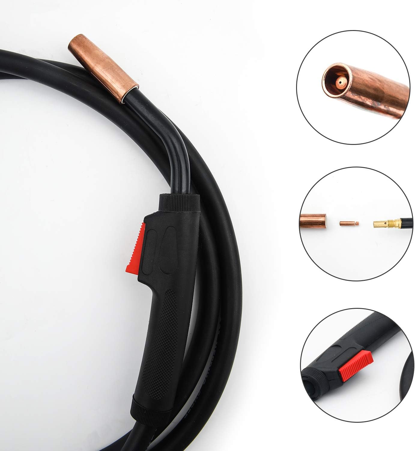
Figure 3: Detailed view of the gun handle, trigger, and front end. This image provides a closer look at the ergonomic handle design, the red trigger mechanism, and the copper gas nozzle and contact tip assembly.

Figure 4: Detailed view of the gun connector assembly. This image shows the brass components and electrical connections at the end of the welding cable, which interface with the welding machine.
4. Setup
Proper setup is crucial for safe and effective welding. Ensure your welding machine is turned off and unplugged before proceeding.
- Connect the Gun to the Welder: Align the gun connector with the corresponding receptacle on your MIG welding machine. Push firmly until it clicks into place or is securely fastened. Ensure the small control wire connector is also properly seated.
- Install Welding Wire: Follow your welding machine's instructions for loading the welding wire spool. Feed the wire through the machine's drive rollers and into the gun's liner.
- Install Contact Tip and Nozzle: Ensure the correct size contact tip for your welding wire diameter (0.024"-0.031" or 0.6mm-0.8mm) is installed. Screw it firmly into the gooseneck. Then, slide the gas nozzle over the gooseneck until it is secure.
- Connect Shielding Gas: If using shielding gas (e.g., CO2), connect the gas hose from your regulator to the gas inlet on your welding machine. Ensure all connections are tight to prevent leaks.
- Ground Clamp: Attach the ground clamp from your welding machine to the workpiece or welding table, ensuring a clean, bare metal connection.

Figure 5: Close-up of the gun connector and its mating part. This image illustrates the design of the connector, which ensures a secure and proper electrical and gas connection to the welding machine.
5. Operating Instructions
Once the setup is complete and all safety precautions are in place, you can begin welding.
- Power On: Turn on your welding machine.
- Set Welding Parameters: Adjust the voltage, wire feed speed, and gas flow rate on your welding machine according to the material thickness and type of wire being used. Refer to your welding machine's manual or a welding chart for recommended settings.
- Purge Gas (if applicable): Briefly press the trigger with the gun pointed away from yourself and others to purge any air from the gas line.
- Position the Gun: Hold the gun firmly with a comfortable grip. Position the contact tip approximately 1/4 to 3/8 inch (6-10 mm) from the workpiece. Maintain a consistent gun angle (typically 10-15 degrees push or drag angle depending on the process).
- Initiate Arc: Press the trigger to start the wire feed and gas flow. The arc will ignite when the wire touches the grounded workpiece.
- Weld: Move the gun steadily along the joint, maintaining a consistent travel speed and arc length. Observe the weld puddle to ensure proper penetration and bead formation.
- Terminate Arc: Release the trigger to stop the wire feed and gas flow.
- Cool Down: Allow the workpiece and gun components to cool before handling.

Figure 6: Close-up of the gun handle and trigger. This image highlights the ergonomic design of the handle and the placement of the trigger, which is used to initiate the welding process.
6. Maintenance
Regular maintenance extends the life of your MIG gun and ensures consistent welding performance. Always disconnect power to the welding machine before performing maintenance.
- Clean Gas Nozzle: Regularly remove spatter from inside and outside the gas nozzle. Use spatter spray to prevent buildup. Replace if damaged or clogged.
- Inspect Contact Tip: Check the contact tip for wear, enlargement of the bore, or excessive spatter. Replace if worn to ensure good electrical contact and consistent wire feeding.
- Check Liner: Periodically check the wire liner for kinks, clogs, or excessive wear. A worn liner can cause erratic wire feeding. If wire feeding issues persist after checking other components, the liner may need replacement.
- Inspect Cable: Examine the welding cable for cuts, abrasions, or damage to the outer jacket. The abrasion-resistant, extruded rubber jacket is designed for durability, but inspect it regularly.
- Clean Gun Connector: Keep the gun connector pins and receptacle clean and free of debris to ensure good electrical contact.

Figure 7: Close-up of the cable strain relief. This image shows the protective spring coil at the base of the connector, designed to prevent kinking and extend the life of the welding cable.
7. Troubleshooting
This section provides solutions to common issues you might encounter.
| Problem | Possible Cause | Solution |
|---|---|---|
| No wire feed | Kinked liner, wrong contact tip size, drive roller tension incorrect, wire spool tangled, trigger not working. | Check liner for obstructions. Ensure correct contact tip. Adjust drive roller tension. Untangle wire spool. Check gun trigger connection. |
| Poor arc stability | Worn contact tip, poor ground connection, incorrect gas flow, dirty workpiece. | Replace contact tip. Clean and secure ground clamp. Check gas flow and connections. Clean workpiece surface. |
| Excessive spatter | Incorrect voltage/wire speed, insufficient gas flow, dirty workpiece, worn contact tip. | Adjust welding parameters. Increase gas flow. Clean workpiece. Replace contact tip. |
| No gas flow | Empty gas cylinder, regulator off, gas hose kinked/leaking, solenoid valve issue. | Check gas cylinder level. Open regulator valve. Inspect hose for damage. Consult welding machine manual for solenoid. |
| Overheating gun | Exceeding duty cycle, poor electrical connections, damaged cable. | Allow gun to cool. Reduce welding time. Check all connections for tightness. Inspect cable for damage. |
8. Specifications
Technical specifications for the NEW Jia Qun Lincoln Magnum 100L (K530-6) Compatible MIG Welding Gun Torch.
| Feature | Specification |
|---|---|
| Model Number | K530-6 |
| Amperage Rating | 100 Amp |
| Duty Cycle | 40% with CO2 gas |
| Cable Length | 10 feet (3 meters) |
| Compatible Wire Diameter | 0.024" - 0.031" (0.6mm - 0.8mm) |
| Material | Copper ABS (Molded high heat resistant material, abrasion-resistant rubber jacket) |
| Color | Black |
| Item Weight | 1.54 kg |
| Parcel Dimensions | 31.7 x 28.5 x 6.4 cm |
| UPC | 791306397351 |
9. Warranty and Support
For warranty information or technical support regarding your NEW Jia Qun MIG Welding Gun Torch, please contact the seller or manufacturer directly through the platform where the product was purchased. Ensure you have your purchase details and model number (K530-6) available when contacting support.
Ask a question about this manual
Ask about setup, troubleshooting, compatibility, parts, safety, or missing instructions. Manuals+ will review the question and use this page’s manual context to help answer it.