1. Introduction
This manual provides essential instructions for the installation, operation, and maintenance of the Sensor Switch NADR-L400 nLIGHT Demand Response Client Interface. Please read this manual thoroughly before attempting to install or operate the device to ensure proper function and safety.
2. Product Overview
The Sensor Switch NADR-L400 is an nLIGHT Demand Response Client Interface designed for integration with nLIGHT Systems. It facilitates communication and control within a networked lighting environment, operating at 5 VDC with a current rating of 1500 mA. The device features a Micro USB power connector and an RJ45 connection for nLIGHT system integration.
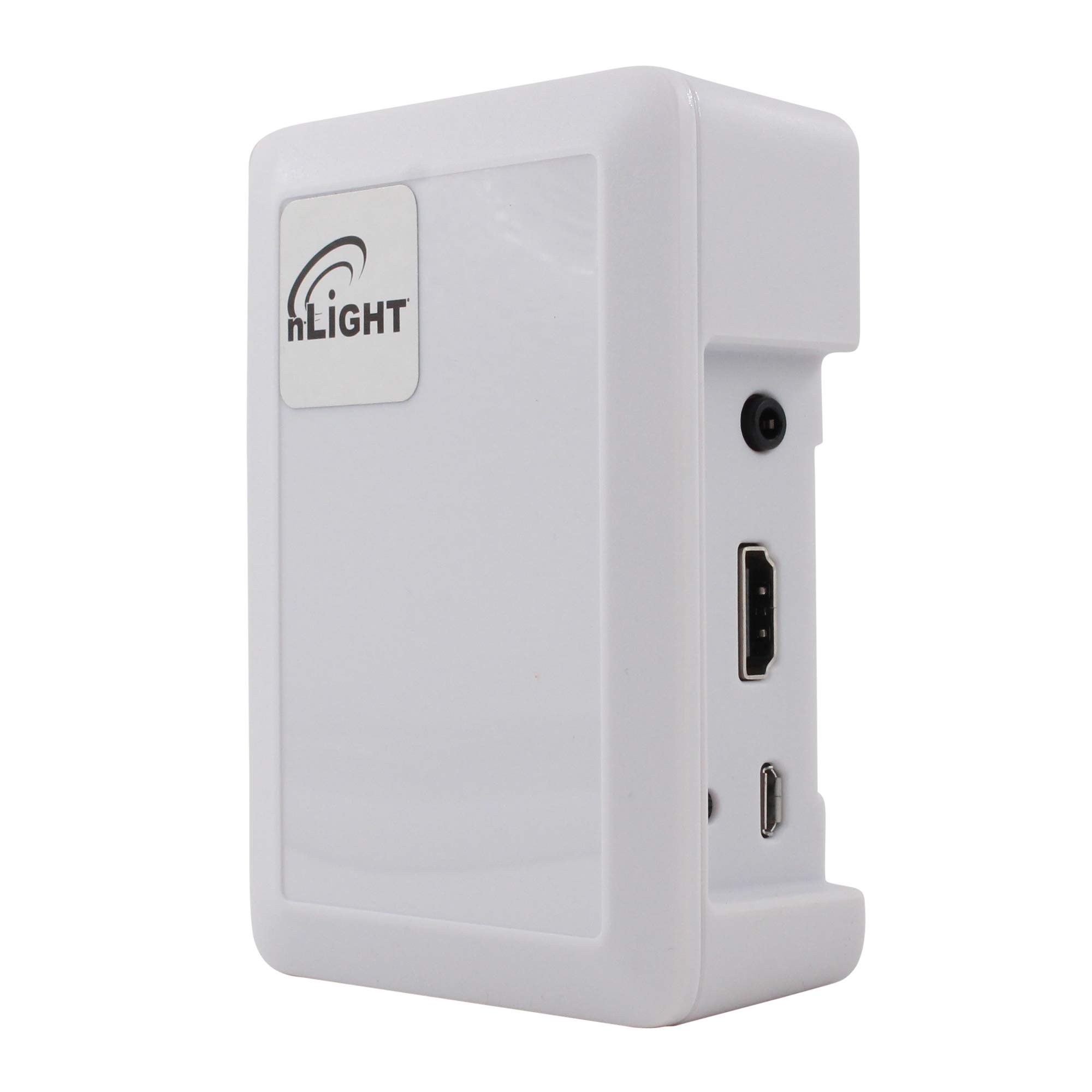
Figure 1: Sensor Switch NADR-L400 nLIGHT Demand Response Client Interface. This image displays the front view of the white interface unit, highlighting its compact design and connection ports.
Key Features:
- 5 VDC, 1500 mA power input.
- Specifically designed for nLIGHT Systems.
- RJ45 connection for nLIGHT network integration.
- Micro USB power connection.
3. Safety Information
Please observe the following safety precautions:
- Electrical Safety: Ensure all power connections are made correctly and securely. Use only the specified 5 VDC power source.
- Installation: Installation should be performed by qualified personnel in accordance with all local and national electrical codes.
- Environment: Do not expose the device to moisture, extreme temperatures, or corrosive environments.
- Servicing: There are no user-serviceable parts inside. Refer all servicing to qualified service personnel.
4. Setup
Follow these steps to set up your NADR-L400 client interface:
- Mounting: Choose a suitable location for the device, ensuring it is protected from environmental hazards and allows for proper cable routing.
- Connect to nLIGHT System: Connect an RJ45 cable from the NADR-L400 to an available nLIGHT network port. Ensure the connection is secure.
- Power Connection: Connect a 5 VDC power supply to the Micro USB power connector on the NADR-L400. Use a power supply that meets the 1500 mA requirement.
- Verification: Once powered, observe any indicator lights on the device to confirm it is receiving power and communicating with the nLIGHT system. Refer to your nLIGHT system documentation for specific indicator light behaviors.
5. Operating Instructions
The NADR-L400 functions as an interface within an nLIGHT Demand Response system. Its operation is primarily managed by the central nLIGHT control system. Once properly installed and connected, the device will automatically communicate with the nLIGHT network to facilitate demand response commands.
- System Integration: The NADR-L400 acts as a bridge, allowing the nLIGHT system to send and receive demand response signals.
- Status Monitoring: Monitor the status of the device through the nLIGHT system's management interface.
- No Direct User Control: This device does not feature direct user controls. All operational parameters are configured and managed via the connected nLIGHT system.
6. Maintenance
The Sensor Switch NADR-L400 requires minimal maintenance to ensure continued reliable operation.
- Cleaning: Periodically clean the exterior of the device with a soft, dry cloth. Do not use liquid cleaners or abrasive materials.
- Inspections: Regularly inspect all cable connections (RJ45 and Micro USB) to ensure they are secure and free from damage.
- Firmware Updates: Any firmware updates for the device would typically be managed through the nLIGHT system. Consult your nLIGHT system documentation or support for information on firmware management.
7. Troubleshooting
If you encounter issues with your NADR-L400, refer to the following common problems and solutions:
| Problem | Possible Cause | Solution |
|---|---|---|
| Device not powering on | No power to Micro USB port; faulty power supply; loose connection. | Verify power supply is connected and functional. Check Micro USB cable for damage and ensure it is securely plugged in. |
| No communication with nLIGHT system | Faulty RJ45 cable; incorrect RJ45 connection; nLIGHT system issue. | Ensure RJ45 cable is securely connected at both ends. Try a different RJ45 cable. Verify the nLIGHT system is operational. |
| Intermittent operation | Loose connections; power fluctuations. | Check all power and network connections for tightness. Ensure a stable power source. |
If the problem persists after attempting these solutions, contact Sensor Switch technical support.
8. Specifications
| Attribute | Value |
|---|---|
| Model Number | NADR-L400 |
| Manufacturer | Sensor Switch |
| Power Source | Plug-in Electric |
| Voltage | 5 Volts DC |
| Current | 1500 mA |
| Connectivity | RJ45 (nLIGHT System), Micro USB (Power) |
| Color | White |
| Product Dimensions | 4 x 4 x 3 inches |
| Item Weight | 1 pound |
9. Warranty and Support
For warranty information and technical support, please refer to the official Sensor Switch website or contact your authorized distributor. Keep your purchase receipt for warranty claims.


