1. Introduction
Thank you for choosing the ANENG Q1 9999 Counts True RMS Digital Multimeter. This device is designed for safe and accurate measurement of various electrical parameters. It features True RMS measurement, Non-Contact Voltage (NCV) detection, auto/manual ranging, and an EBTN black display with an analog bar graph for enhanced readability. Please read this manual thoroughly before use to ensure proper operation and safety.
2. Safety Information
WARNING: To avoid possible electric shock, fire, or personal injury, please read all safety information before you use the product.
- Always ensure the multimeter is in the correct function and range for the measurement being performed.
- Do not exceed the maximum input values for any function.
- Inspect test leads for damaged insulation or exposed metal before use. Replace if damaged.
- Do not use the multimeter if it appears damaged or if it is not operating properly.
- Be cautious when working with voltages above 30V AC RMS, 42V peak, or 60V DC. These voltages pose a shock hazard.
- Always disconnect the test leads from the circuit before changing functions or ranges.
- Replace batteries as soon as the low battery indicator appears to avoid incorrect readings.
- Adhere to local and national safety codes.
3. Product Overview
The ANENG Q1 multimeter is a versatile tool for electrical measurements. Below is an image illustrating the device and its included accessories.

Image 3.1: ANENG Q1 Digital Multimeter and included accessories, including test leads, temperature probe, and storage bag.
The device features a large EBTN display, function buttons, and input jacks for test leads.

Image 3.2: Front view of the ANENG Q1 Multimeter, highlighting the display, function buttons, and input terminals.
4. Setup
4.1 Battery Installation
The ANENG Q1 multimeter requires two 1.5V AA batteries (not included). To install or replace batteries:
- Ensure the multimeter is powered off and disconnect all test leads.
- Locate the battery compartment cover on the back of the device.
- Use a screwdriver to loosen the screw securing the cover.
- Remove the cover and insert two AA batteries, observing correct polarity (+/-).
- Replace the battery compartment cover and tighten the screw.
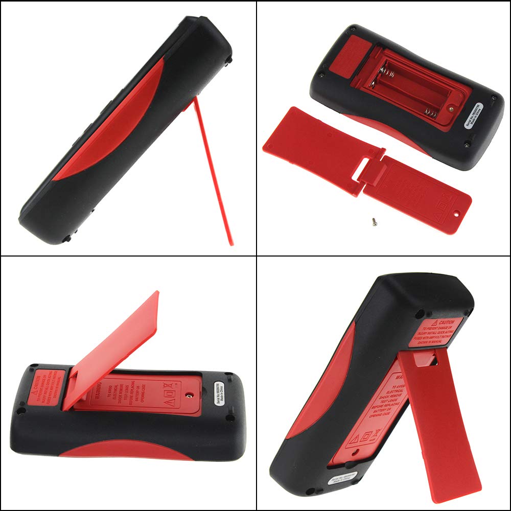
Image 4.1: Rear view of the multimeter, illustrating the battery compartment and the integrated kickstand.
4.2 Connecting Test Leads
The multimeter comes with two standard test probes and a 16-in-1 multifunctional test line set. Always connect the black test lead to the COM (Common) jack. Connect the red test lead to the appropriate input jack based on the measurement type:
- VΩHz-+ jack for Voltage, Resistance, Frequency, Diode, and Continuity measurements.
- mA jack for milliampere current measurements.
- μA jack for microampere current measurements.
- 10A MAX jack for high current measurements (up to 10A).

Image 4.2: Included test leads and various accessories, such as alligator clips and fine-point probes.
5. Operating Instructions
The ANENG Q1 features both auto-ranging and manual-ranging capabilities. Press the RANGE button to switch between auto and manual modes. In manual mode, press RANGE repeatedly to cycle through available ranges.
5.1 Power On/Off
Press and hold the POWER button (red circle with line) for more than 2 seconds to turn the multimeter on or off. The device also features an Auto Power Off function to conserve battery life.
5.2 Measuring AC/DC Voltage
- Connect the black test lead to the COM jack and the red test lead to the VΩHz-+ jack.
- Turn on the multimeter. The device will typically default to auto-ranging voltage measurement.
- Touch the test probes to the circuit points where voltage is to be measured.
- Read the voltage value on the display. The multimeter automatically detects AC or DC voltage.
5.3 Measuring AC/DC Current
- IMPORTANT: Ensure the circuit is de-energized before connecting the multimeter in series.
- Connect the black test lead to the COM jack. Connect the red test lead to the mA, μA, or 10A MAX jack depending on the expected current.
- Insert the multimeter in series with the circuit where current is to be measured.
- Re-energize the circuit.
- Read the current value on the display.
5.4 Measuring Resistance
- Connect the black test lead to the COM jack and the red test lead to the VΩHz-+ jack.
- Ensure the circuit or component is de-energized before measuring resistance.
- Touch the test probes across the component to be measured.
- Read the resistance value on the display.
5.5 Measuring Capacitance
- Connect the black test lead to the COM jack and the red test lead to the VΩHz-+ jack.
- Ensure the capacitor is fully discharged before measurement to avoid damage to the multimeter.
- Touch the test probes across the capacitor terminals.
- Read the capacitance value on the display.
5.6 Measuring Temperature
- Connect the temperature sensor (thermocouple) to the VΩHz-+ and COM jacks, observing polarity if applicable.
- Place the tip of the temperature sensor on or near the object whose temperature is to be measured.
- Read the temperature value on the display. The unit can be switched between Celsius and Fahrenheit.
5.7 Non-Contact Voltage (NCV) Detection
The NCV function allows for detection of AC voltage without direct contact with conductors.
- Press the NCV button to activate the NCV mode.
- Move the top of the multimeter near the conductor or outlet.
- The display will show an increasing number of bars and an audible beep will indicate the presence and strength of AC voltage.

Image 5.1: The multimeter performing a Non-Contact Voltage (NCV) test near a power strip, indicated by the signal icon on the display.
5.8 Diode Test and Continuity
These functions are typically accessed through the VΩHz-+ jack and a dedicated button or range selection.
- Diode Test: Connect the red lead to the anode and the black lead to the cathode of the diode. The display will show the forward voltage drop. Reverse the leads to check for open circuit.
- Continuity Test: Touch the probes to the two points of the circuit. A continuous beep indicates a low resistance path (continuity).
6. Maintenance
6.1 Cleaning
Wipe the case with a damp cloth and mild detergent. Do not use abrasives or solvents. Keep the input terminals free of dirt and moisture.
6.2 Battery Replacement
Refer to Section 4.1 for battery replacement instructions. Replace batteries promptly when the low battery indicator appears on the display.
6.3 Fuse Replacement
The multimeter is protected by internal fuses. If the current measurement function stops working, the fuse may need replacement. Fuse replacement should only be performed by qualified personnel. Refer to the specifications for fuse ratings.
7. Troubleshooting
- No display or faint display: Check battery installation and charge. Replace batteries if necessary.
- Incorrect readings: Ensure test leads are properly connected, the correct function/range is selected, and the batteries are not low.
- Current measurement not working: Check the fuse. If blown, replace with a fuse of the correct rating.
- "OL" or "OVER" on display: Indicates an overload or out-of-range measurement. Select a higher range or ensure the input is within the device's limits.
8. Specifications
| Parameter | Range/Value |
|---|---|
| Display Type | Digital Display, 9999 Counts, EBTN Black Display, Analog Bar Graph |
| Capacitance | 9.99nF / 99.99nF / 999.9nF / 9.99µF / 99.99µF / 999.9µF / 9.999mF |
| Voltage (AC/DC) | 99.99mV / 999.9mV / 9.999V / 99.99V / 999.9V |
| Current (AC/DC) | 99.99µA / 999.9µA / 99.99mA / 999.9mA / 9.999A |
| Resistance | 99.99Ω / 999.9Ω / 9.999kΩ / 99.99kΩ / 999.9kΩ / 9.999MΩ / 99.99MΩ |
| Frequency | 99.99Hz / 999.9Hz / 9.999kHz / 99.99kHz / 999.9kHz / 5MHz |
| Temperature | -20°C ~ 1000°C / -4°F ~ 1832°F |
| Diode Test | Yes |
| Continuity | Yes |
| Duty Cycle | 1% - 99% |
| Sampling Rate | 3 times per second |
| Power | 2 x 1.5V AA batteries |
| Operating Mode | Auto/Manual Range |
| Operating Temperature | 0-40°C |
| Operating Humidity | ≤ 75% RH |
| Storage Condition | -20 ~ 60°C |
| Storage Humidity | ≤ 80% RH |
| Safety Rating | 600V CAT III, 1000V CAT II (inferred) |
9. Warranty and Support
Specific warranty information is not provided in the product details. For warranty claims or technical support, please contact the retailer or manufacturer directly. Keep your purchase receipt as proof of purchase.


