
YOTON T48L, T24L, T48LX, T24LX Control Panel Keyboard
YOTON Control Panel Keyboard User Manual
For Kuco Teneth T48L, T24L, T48LX, T24LX Series Cutting Plotters
1. Introduction
This manual provides comprehensive instructions for the installation, operation, and maintenance of the YOTON Control Panel Keyboard, designed for use with Kuco Teneth T48L, T24L, T48LX, and T24LX series cutting plotters. Please read this manual thoroughly before use to ensure proper functionality and longevity of the product.
2. Product Overview
The YOTON Control Panel Keyboard serves as a direct replacement or upgrade for the control interface of specified Kuco Teneth cutting plotters. It features a user-friendly button layout and a display screen for efficient plotter operation.
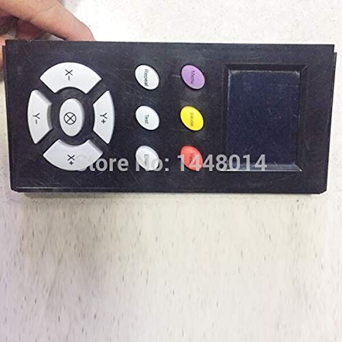
Figure 2.1: Front View of Control Panel. This image displays the front of the control panel, showing the directional arrow keys (X-, X+, Y-, Y+), origin set button, repeat, test, pause, menu, and enter buttons, along with the integrated display screen.
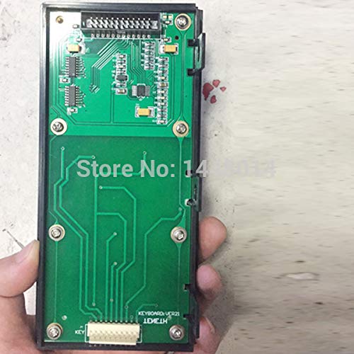
Figure 2.2: Back View of Control Panel. This image shows the reverse side of the control panel, revealing the circuit board, connectors, and mounting points. This view is important for understanding the internal components and connection interface.
3. Setup and Installation
Before proceeding with installation, ensure the cutting plotter is powered off and disconnected from the main power supply. Refer to your plotter's original service manual for specific instructions on accessing and replacing the control panel.
3.1. Tools Required
- Small Phillips head screwdriver
- Anti-static wrist strap (recommended)
3.2. Installation Steps
- Power Off: Ensure the cutting plotter is completely powered off and unplugged from the electrical outlet.
- Access Panel: Locate and open the access panel on your cutting plotter that houses the existing control panel. This may involve removing screws or latches.
- Disconnect Old Panel: Carefully disconnect any ribbon cables or power connectors attached to the old control panel. Note their orientation for re-connection.
- Remove Old Panel: Unscrew and remove the old control panel from its mounting bracket.
- Install New Panel: Position the YOTON Control Panel Keyboard into the mounting bracket. Secure it with the screws removed earlier.
- Connect Cables: Reconnect all ribbon cables and power connectors to the new control panel. Ensure connections are firm and correctly oriented. Refer to Figure 2.2 for connector locations on the back of the panel.
- Close Panel: Close and secure the access panel on your cutting plotter.
- Power On: Reconnect the plotter to the power supply and power it on. The new control panel should illuminate and display the plotter's interface.
4. Operating Instructions
The control panel provides intuitive access to your plotter's functions. Familiarize yourself with the button layout as shown in Figure 2.1.
4.1. Button Functions
- Directional Keys (X+, X-, Y+, Y-): Used to move the cutting head or material in the respective directions.
- Origin Set (Center Button): Sets the current position of the cutting head as the new origin point for the cutting job.
- Repeat: Repeats the last cutting job.
- Test: Initiates a small test cut to verify blade pressure and offset settings.
- Pause: Temporarily stops the current cutting operation. Press again to resume.
- Menu: Accesses the plotter's main menu for settings adjustments (e.g., speed, force, offset).
- Enter (often combined with Menu or a separate button): Confirms selections within menus.
- Escape/Back: Navigates back through menu levels or cancels an operation. (Note: This button might be integrated with another or labeled differently depending on the specific plotter model).
4.2. Basic Operation Flow
- Load Material: Load your vinyl or other cutting material into the plotter.
- Position Head: Use the directional keys to move the cutting head to your desired starting point.
- Set Origin: Press the Origin Set button to define the starting point for your cut.
- Adjust Settings (Optional): Press Menu to adjust cutting speed, force, or other parameters as needed. Use directional keys to navigate and Enter to confirm.
- Send Job: Send the cutting job from your design software to the plotter.
- Monitor: Observe the cutting process. Use Pause if necessary.
5. Maintenance
Regular maintenance ensures the longevity and optimal performance of your control panel.
- Cleaning: Gently wipe the surface of the control panel with a soft, dry, lint-free cloth. For stubborn marks, slightly dampen the cloth with water or a mild, non-abrasive cleaner. Avoid excessive moisture.
- Avoid Liquids: Do not spray cleaning solutions directly onto the panel. Ensure no liquids seep into the buttons or display.
- Environmental Conditions: Operate and store the plotter and control panel in a clean, dry environment, away from direct sunlight, extreme temperatures, and excessive dust.
- Cable Connections: Periodically check that all cables connected to the control panel are secure and free from damage.
6. Troubleshooting
This section addresses common issues you might encounter with the control panel.
| Problem | Possible Cause | Solution |
|---|---|---|
| Control panel does not power on. |
|
|
| Buttons are unresponsive. |
|
|
| Display screen is blank or distorted. |
|
|
If you encounter issues not listed here or if the suggested solutions do not resolve the problem, please contact customer support.
7. Specifications
- Product Type: Control Panel Keyboard
- Compatibility: Kuco Teneth T48L, T24L, T48LX, T24LX Series Cutting Plotters
- Manufacturer: YOTON
- ASIN: B07RKWGXNG
- Part Number: YTN-D41D8CD98F00B204E9800998ECF8427E (Manufacturer reference)
8. Warranty and Support
For warranty information, please refer to the terms and conditions provided at the point of purchase or contact your retailer. For technical support or inquiries regarding this product, please contact YOTON customer service through the official channels provided by your seller or on the YOTON brand store page on Amazon.
YOTON Store Link: https://www.amazon.ca/stores/YOTON/page/79E49917-1909-4379-9785-84583D0518D6
Ask a question about this manual
Ask about setup, troubleshooting, compatibility, parts, safety, or missing instructions. Manuals+ will review the question and use this page’s manual context to help answer it.