1. Introduction
This manual provides essential information for the proper installation, operation, and maintenance of the Seeku FX1N-30MR PLC Industrial Control Board. Please read this manual thoroughly before using the product to ensure safe and efficient operation. Keep this manual for future reference.
2. Safety Information
Always observe the following safety precautions to prevent personal injury and damage to the equipment:
- Ensure the power supply is disconnected before performing any wiring or maintenance.
- Only qualified personnel should install, operate, and maintain this device.
- Do not operate the PLC in environments exceeding its specified operating temperature or humidity ranges.
- Avoid exposing the device to direct sunlight, excessive dust, corrosive gases, or strong vibrations.
- Verify all wiring connections are correct and secure before applying power. Incorrect wiring can cause damage to the PLC or connected equipment.
3. Product Overview
The Seeku FX1N-30MR is a compact and reliable Programmable Logic Controller (PLC) designed for industrial automation applications. It features 16 digital inputs and 14 relay outputs, along with analog input/output capabilities and communication interfaces.
Key Features:
- High-quality chip for stable performance and power-off protection.
- Integrated RS-232 and RS-485 communication interfaces.
- Built-in real-time clock and Run/Stop switch.
- Analog input (3AD 0-10V) and analog output (2DA 0-10V).
- Compact size for space-saving installations.
Component Identification:

Figure 3.1: Front view of the FX1N-30MR PLC, highlighting the input (X) and output (Y) terminals, RS-232 port, and power input.
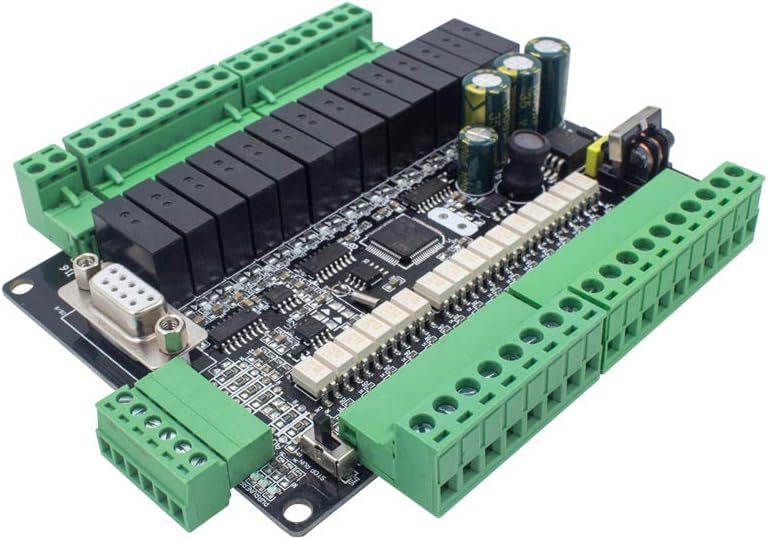
Figure 3.2: Angled view of the PLC, illustrating the accessible terminal blocks for wiring and the communication port.
4. Specifications
| Feature | Description |
|---|---|
| Model Number | FX1N-30MR |
| Power Supply Voltage | DC24V |
| Number of Digital Inputs | 16 |
| Input Type | Digital |
| Number of Outputs | 14 (Relay) |
| Output Type | Relay |
| Output Current | 5A |
| Power-off Protection | Supported |
| Analog Input | 3AD 0-10V |
| Analog Output | 2DA 0-10V |
| High Speed Input | 2 Channels 3K |
| High Speed Output | No |
| Communication | RS232, RS485 |
| Real-time Clock | Built-in |
| Run/Stop Switch | Built-in |
| Program Capacity | 8000 Steps EEPROM |
| Programming Language | Ladder Logic |
| Programming Software | GX Developer or GX Works2 |
| Programming Interface | Computer |
| Operating Temperature | 0°C ~ +55°C |
| Dimensions | 125 x 90 x 40mm |
| Hole Dimension | 117 x 82mm |
| Material | Copper |
Dimensions Diagram:

Figure 4.1: Detailed dimensions of the FX1N-30MR PLC for mounting and installation planning.
5. Installation & Wiring
Mounting:
The FX1N-30MR PLC is designed for easy installation. It includes a shell and base for secure mounting. Use the provided hole dimensions (117 x 82mm) for precise placement.
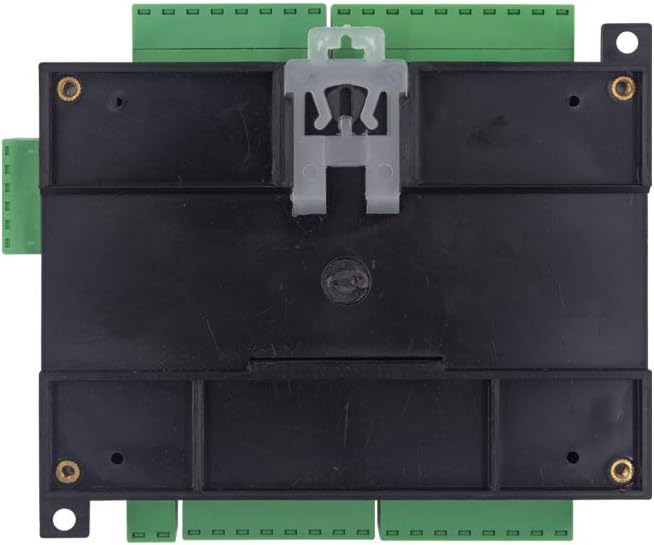
Figure 5.1: Rear view of the PLC, illustrating the mounting mechanism for panel or DIN rail installation.
Wiring Instructions:
All wiring should be performed with the power disconnected. Refer to the wiring diagram below for correct connections. Ensure all wires are properly stripped and securely fastened in the terminal blocks.
- Power Supply: Connect DC24V to the designated power terminals.
- Digital Inputs (X0-X17): Connect your digital input devices (e.g., switches, sensors) to these terminals.
- Digital Outputs (Y0-Y15): Connect your relay-controlled devices (e.g., contactors, indicator lights) to these terminals. The outputs are relay type with a 5A current rating.
- Analog Inputs (AD0, AD1, AD2): Connect 0-10V analog signals to these terminals.
- Analog Outputs (DA1, DA2): These terminals provide 0-10V analog output signals.
- Communication Ports (RS232, RS485): Use these ports for connecting to a computer or other communication devices.

Figure 5.2: Comprehensive wiring diagram for the FX1N-30MR PLC.
6. Programming
The FX1N-30MR PLC is programmed using Ladder Logic. Programming is typically done via a computer connected to the PLC's RS232 or RS485 interface.
Software Requirements:
- Compatible programming software includes GX Developer or GX Works2.
Programming Steps (General):
- Install the appropriate programming software (GX Developer or GX Works2) on your computer.
- Connect your computer to the PLC using a compatible RS232 or RS485 cable.
- Configure the communication settings in the software to match the PLC's settings.
- Create your Ladder Logic program according to your application requirements.
- Download the program to the PLC's 8000-step EEPROM memory.
- Test the program thoroughly to ensure correct operation.
7. Operation
Run/Stop Switch:
The PLC features a built-in Run/Stop switch. This switch allows you to manually control the operational state of the PLC program without needing to connect to a computer.
- RUN Position: The PLC executes the loaded program.
- STOP Position: The PLC halts program execution. This is useful for debugging or making changes.
Real-time Clock:
The integrated real-time clock allows for time-based operations within your PLC program, such as scheduling events or logging data with timestamps.
8. Maintenance
The Seeku FX1N-30MR PLC is designed for reliability and requires minimal maintenance. However, regular checks can extend its lifespan and ensure optimal performance:
- Keep the PLC clean and free from dust and debris. Use a soft, dry cloth for cleaning.
- Periodically check all wiring connections for tightness and signs of corrosion.
- Ensure proper ventilation around the PLC to prevent overheating.
- Inspect for any physical damage to the casing or terminals.
9. Troubleshooting
If you encounter issues with your FX1N-30MR PLC, consider the following common troubleshooting steps:
- No Power: Verify the DC24V power supply is connected correctly and providing the specified voltage. Check for blown fuses in the power circuit.
- Inputs Not Responding: Check the wiring of the input devices. Ensure the input signals are within the specified voltage range. Verify the PLC is in RUN mode.
- Outputs Not Activating: Check the wiring of the output devices. Ensure the output devices are receiving power. Verify the PLC program logic for the output. Check if the PLC is in RUN mode.
- Communication Errors: Verify the communication cable is correctly connected. Check the communication settings (baud rate, data bits, parity, stop bits) in your programming software and ensure they match the PLC's settings.
- Program Download Failure: Ensure the PLC is in STOP mode before attempting to download a new program. Check communication settings.
If problems persist, consult the programming software documentation or seek professional assistance.
10. Warranty and Support
For specific warranty information, please refer to the product's purchase documentation or contact your vendor. For technical support, please reach out to the manufacturer or your authorized distributor.