
V BESTLIFE VBESTLIFEi2upgs5kv8
VBESTLIFE 433Mhz Wireless Remote Control Switch User Manual
DC 12V 1CH Relay Receiver Module & RF Transmitter Remote Controls
1. Introduction
This manual provides detailed instructions for the installation, operation, and programming of your VBESTLIFE 433Mhz Wireless Remote Control Switch. This system consists of a DC 12V 1-channel relay receiver module and an RF transmitter remote control, designed for various applications requiring remote switching of electrical devices.
2. Safety Information
- Ensure all power is disconnected before performing any wiring or installation.
- This device operates on DC 12V. Connecting it to higher voltages may cause damage or injury.
- Do not expose the device to moisture, extreme temperatures, or corrosive environments.
- Installation should be performed by qualified personnel if you are unsure about electrical wiring.
- Keep the remote control out of reach of children.
3. Package Contents
- 1 x DC 12V 1-Channel Relay Receiver Module
- 1 x 433Mhz RF Transmitter Remote Control
4. Product Overview
The VBESTLIFE wireless remote control system allows for convenient remote operation of various electrical loads. The receiver module features a single relay output and a learning button for pairing with the remote. The compact remote control provides a single button for activation.

Figure 1: The VBESTLIFE 433Mhz wireless remote control and its corresponding 1-channel relay receiver module.

Figure 2: The receiver module with its cover removed, revealing the relay, antenna, and screw terminals for power and output connections.

Figure 3: A detailed view of the receiver module's circuit board, highlighting the relay, capacitors, and the learning button (small black button near the antenna coil).
5. Specifications
| Feature | Specification |
|---|---|
| Brand | V BESTLIFE |
| Model Number | VBESTLIFEi2upgs5kv8 |
| Operating Voltage | DC 12V |
| Operating Frequency | 433Mhz |
| Relay Channels | 1 Channel |
| Contact Material | Silver |
| Contact Type | Normally Open (NO) |
| Current Rating | 10 Amps |
| Maximum Switching Current | 10 Amps |
| Maximum Switching Voltage | 12 Volts (DC) / 250 Volts (AC) |
| Remote Control Distance | Up to 100m (open area) |
| Mounting Type | Surface Mount |
| Dimensions | Approximately 0.39 x 0.39 x 0.39 inches (Receiver Module) |
| Item Weight | Approximately 0.81 ounces |
6. Setup and Wiring
Before wiring, ensure the power supply is disconnected. The receiver module has screw terminals for power input and relay output.
6.1 Wiring the Receiver Module
- Power Input: Connect your DC 12V power supply to the terminals labeled DC+ (positive) and DC- (negative).
- Relay Output: The relay has three terminals: NO (Normally Open), COM (Common), and NC (Normally Closed). For most applications, you will use NO and COM.
- To switch a load (e.g., a light, motor) that needs to be turned ON when the remote button is pressed: Connect one wire from your load to the COM terminal and the other wire from your load to the NO terminal. The power source for the load should be connected appropriately.
- Ensure all connections are secure to prevent short circuits.
Figure 4: The receiver module showing the DC 12V input terminals and the relay output terminals (NO, COM, NC) for connecting your device.
7. Programming the Remote Control (Learning Code)
The receiver module uses a learning code function to pair with the remote control and set the operating mode. The module supports Momentary and Toggle modes.
7.1 Clearing Existing Codes
Before programming a new remote or changing the operating mode, it is recommended to clear any previously stored codes.
- Press and hold the learning button (small black button on the receiver PCB, refer to Figure 3) for approximately 8 seconds until the indicator LED flashes rapidly and then turns off. This indicates that all stored remote codes have been cleared.
7.2 Setting Operating Modes
After clearing codes, you can program the remote control to operate in one of the following modes:
7.2.1 Momentary Mode (Jog)
In Momentary mode, the relay activates only while the remote button is pressed and held. It deactivates upon release.
- Press the learning button on the receiver module once. The indicator LED will turn on.
- Press the button on your remote control. The indicator LED on the receiver will flash three times and then turn off, indicating successful pairing in Momentary mode.
7.2.2 Toggle Mode (Self-Locking)
In Toggle mode, pressing the remote button once activates the relay, and pressing the same button again deactivates it.
- Press the learning button on the receiver module twice. The indicator LED will turn on.
- Press the button on your remote control. The indicator LED on the receiver will flash three times and then turn off, indicating successful pairing in Toggle mode.
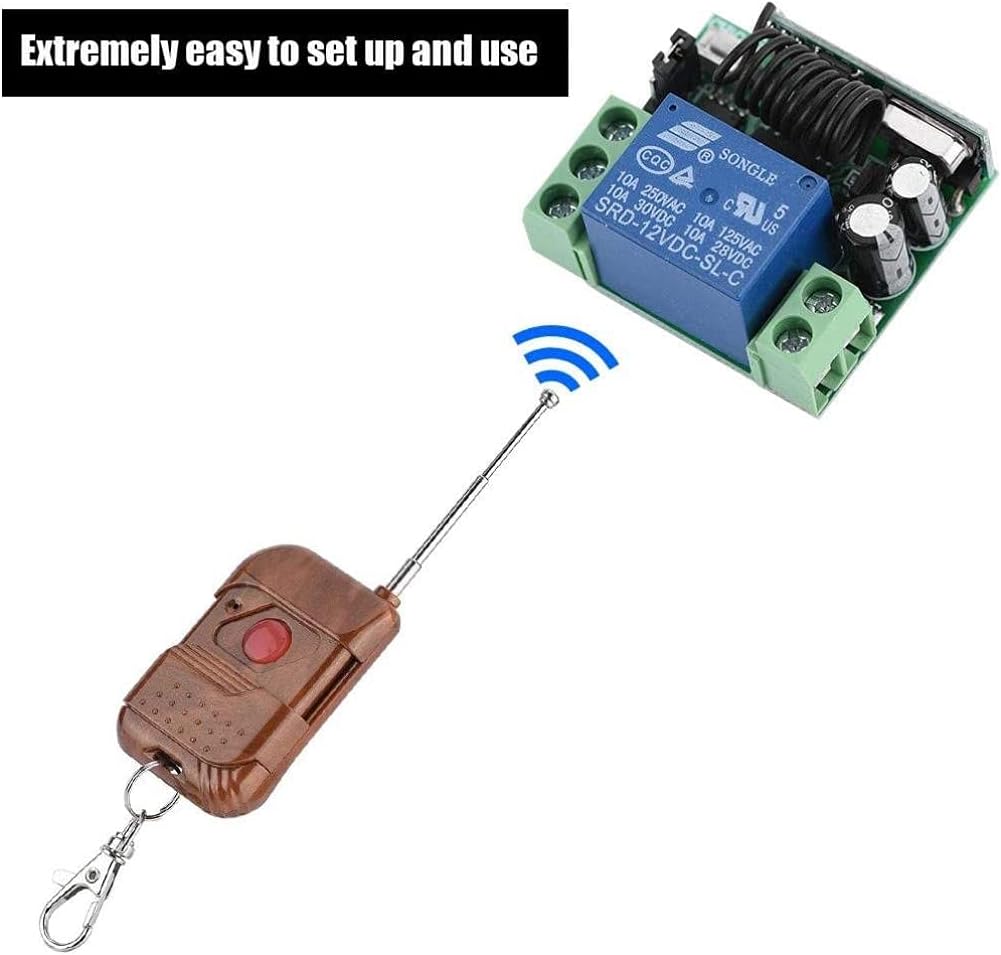
Figure 5: The remote control transmitting a signal to the receiver module, demonstrating the wireless operation after successful pairing.
8. Operating Instructions
Once the remote control is successfully paired with the receiver module and the desired operating mode is set:
- Momentary Mode: Press and hold the button on the remote control to activate the connected device. Release the button to deactivate.
- Toggle Mode: Press the button on the remote control once to activate the connected device. Press the same button again to deactivate.

Figure 6: An example application showing the wireless remote control being used to operate a door, highlighting its convenience.
9. Maintenance
- Keep the receiver module and remote control clean and dry.
- Avoid dropping the devices or subjecting them to strong impacts.
- If the remote control range decreases significantly, consider replacing the battery inside the remote (typically a 23A/12V battery, though not explicitly stated for this model, it's common for such remotes).

Figure 7: The remote control with its antenna extended, which can help optimize signal range.
10. Troubleshooting
- Device not responding to remote:
- Check if the receiver module is powered correctly (indicator LED should be on or flash during operation).
- Ensure the remote control battery is not depleted.
- Re-program the remote control to the receiver module (refer to Section 7).
- Ensure there are no strong RF interference sources nearby.
- Short operating range:
- Replace the remote control battery.
- Ensure the receiver's antenna is not obstructed or damaged.
- Avoid metal enclosures around the receiver module, which can block RF signals.
- Relay not switching:
- Verify the wiring connections to the relay output terminals (NO, COM, NC).
- Ensure the load connected to the relay does not exceed the maximum current rating of 10 Amps.
11. Warranty and Support
This product is covered by a standard manufacturer's warranty. For specific warranty terms, technical support, or service inquiries, please refer to the retailer or manufacturer's official website. Keep your purchase receipt for warranty claims.
Ask a question about this manual
Ask about setup, troubleshooting, compatibility, parts, safety, or missing instructions. Manuals+ will review the question and use this page’s manual context to help answer it.