1. Introduction
This manual provides essential information for the safe and efficient installation, operation, and maintenance of the Allen-Bradley 1305-BA06A Adjustable Frequency AC Drive, Series C. Please read this manual thoroughly before attempting to install or operate the drive. Retain this manual for future reference.
2. Safety Information
WARNING: Electrical shock hazard. Only qualified personnel should install, operate, or service this equipment.
- Always disconnect and lock out power before working on the drive or connected equipment.
- Ensure proper grounding of the drive and motor.
- Do not touch electrical components when power is applied.
- Verify all wiring connections are secure and correct before applying power.
- Observe all local and national electrical codes.
3. Product Overview
The Allen-Bradley 1305-BA06A is an adjustable frequency AC drive designed for controlling the speed and torque of AC induction motors. It features a robust design suitable for industrial applications and includes a user-friendly interface with a touchscreen display for parameter adjustment and monitoring.

Image 3.1: Front view of the Allen-Bradley 1305-BA06A AC Drive alongside its user manual.
The drive is engineered for reliable performance, offering precise motor control capabilities. Its compact form factor allows for integration into various control panels and systems.
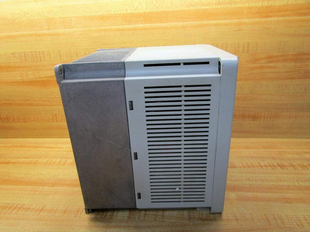
Image 3.2: Side view of the Allen-Bradley 1305-BA06A AC Drive, showing its ventilation design.
4. Setup and Installation
4.1 Mounting
Mount the drive vertically on a flat, stable surface, ensuring adequate clearance for ventilation. Avoid mounting in direct sunlight or near heat sources. Refer to the drive's dimensions for proper enclosure sizing.
4.2 Wiring
All wiring must comply with local and national electrical codes. Use appropriate wire gauges for power and control circuits. Ensure all connections are tight to prevent loose contacts and potential hazards.
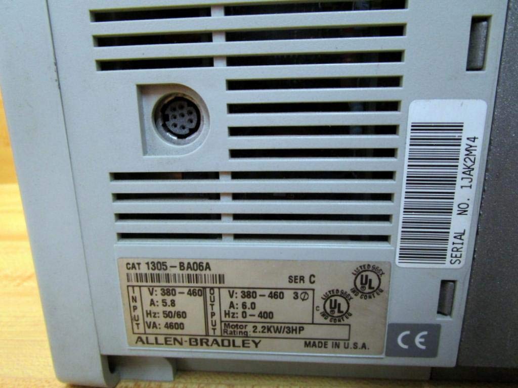
Image 4.1: Rear view of the drive, displaying the product label with input/output specifications and serial number.
4.2.1 Power Connections
- Connect the incoming AC power supply to the designated input terminals.
- Connect the motor leads to the output terminals (U, V, W).
- Ensure proper grounding of the drive chassis and motor frame.
4.2.2 Control Connections
Connect control signals (e.g., start/stop, speed reference) to the appropriate control terminals. The drive features a 9-pin female connection for control interface. Refer to the detailed wiring diagrams in the complete product documentation for specific terminal assignments.
5. Operating Instructions
5.1 Powering On/Off
- To power on, ensure all connections are secure, then apply main power to the drive. The display will illuminate.
- To power off, remove main power from the drive. Wait for the display to turn off completely before performing any service.
5.2 Basic Control Panel Operation
The drive features a control panel with a touchscreen display and dedicated buttons for basic functions:
- ESC: Escape/Cancel button.
- SEL: Select/Enter button.
- ▲ / ▼: Up/Down arrow buttons for navigation and value adjustment.
- JOG: Jog function button.
- START: Initiates motor operation.
- STOP: Halts motor operation.
Use the touchscreen or arrow buttons to navigate menus and adjust parameters. Refer to the drive's programming manual for detailed parameter settings and advanced functions.
6. Maintenance
Regular maintenance ensures optimal performance and extends the lifespan of the drive. Always disconnect power before performing any maintenance.
6.1 Routine Inspection
- Inspect the drive for any signs of physical damage, loose connections, or discoloration.
- Check for dust accumulation on cooling fins and internal components.
6.2 Cleaning
Use compressed air to remove dust from the cooling fins and internal components. Do not use liquid cleaners directly on electrical parts. Ensure the drive is completely dry before reapplying power.

Image 6.1: Bottom view of the drive, highlighting the cooling fins for heat dissipation.
6.3 Cooling System
Ensure that the drive's cooling system, including fans and heat sinks, remains unobstructed and clean. Proper airflow is critical for preventing overheating and maintaining performance.
7. Troubleshooting
This section provides general guidance for common issues. For detailed troubleshooting, refer to the complete product manual or contact technical support.
- No Power/Display Off: Check input power connections, fuses, and circuit breakers.
- Motor Not Running: Verify start command, speed reference, and motor connections. Check for active fault codes on the display.
- Overcurrent/Overvoltage Fault: Inspect motor and load for issues. Check input voltage stability.
- Overheat Fault: Ensure proper ventilation and clean cooling fins. Check ambient temperature.
If an error code appears on the display, record the code and consult the drive's programming manual for specific diagnostic steps.
8. Specifications
| Parameter | Value |
|---|---|
| Model Number | 1305-BA06A |
| Series | C |
| Input Voltage | 380-460V AC |
| Input Current | 5.8 A |
| Input Frequency | 50/60 Hz |
| Input VA | 4600 VA |
| Output Voltage | 380-460V AC |
| Output Current | 6.0 A |
| Output Frequency Range | 0-400 Hz |
| Motor Rating | 2.2 KW / 3 HP |
| Control Connection | 9-Pin Female |
| Product Dimensions | 7 x 7 x 7 inches |
| Item Weight | 8.9 Pounds (4.04 kg) |
| Display Type | Touchscreen |
| Manufacturer | Allen Bradley |
9. Warranty and Support
For information regarding product warranty, please refer to the original purchase documentation or contact your authorized Allen-Bradley distributor. Technical support can be obtained through Allen-Bradley's official channels or your product supplier.


