
Introduction
This manual provides comprehensive instructions for the safe and effective use of the ACEIRMC SOIC8 SOP8 Flash Chip IC Test Clips Socket Adapter Programmer BIOS + CH341A 24 25 Series. This device is designed for reading, erasing, programming, and verifying various EEPROM and BIOS chips, primarily supporting 24, 25, and 93 series chips. It is an essential tool for tasks such as BIOS recovery, firmware updates, and data backup for compatible integrated circuits.
Safety Information
Always observe the following safety precautions to prevent damage to the device, the chips being programmed, or personal injury:
- Ensure proper grounding when working with electronic components to prevent electrostatic discharge (ESD).
- Disconnect power from the target device before connecting or disconnecting the test clip or programmer.
- Verify chip pin orientation and connections carefully before applying power or initiating programming. Incorrect connections can cause permanent damage.
- Do not exceed the specified voltage or current ratings for the programmer or the chips.
- Keep the device away from moisture, extreme temperatures, and corrosive environments.
- This device is intended for use by individuals with appropriate technical knowledge of electronics and chip programming.
Package Contents
Verify that all items listed below are present in your package:
- 1x CH341A USB Programmer Module
- 1x SOIC8 SOP8 Test Clip with Cable
- 1x SOP8 to DIP8 Adapter (150mil)
- 1x SOP8 to DIP8 Adapter (200-208mil)
- 2x Pin Headers (for adapters)
- 1x Dual-Use Board (for soldering 8/16 PIN chips)

Figure 1: Complete package contents of the ACEIRMC CH341A programmer kit.
Product Overview
The ACEIRMC programmer kit consists of a CH341A USB programmer and various accessories designed to facilitate EEPROM and BIOS chip programming. Key components include:
- CH341A USB Programmer: The main unit, featuring a USB interface for connection to a computer, a ZIF (Zero Insertion Force) socket for direct chip programming, and a programming/TTL conversion interface. It includes R&W and power indicators, a 500mA self-recovery fuse, and a 12M crystal oscillator for stable operation.
- SOIC8 SOP8 Test Clip: Allows for in-circuit programming of SOP8 chips without desoldering them from the board.
- SOP8 to DIP8 Adapters: For adapting SOP8 chips to the DIP8 socket on the programmer.
- Dual-Use Board: A versatile board that can be used for soldering 8-pin or 16-pin chips for programming.

Figure 2: Detailed features of the CH341A USB Programmer.
Setup
1. Driver Installation
Before connecting the CH341A programmer to your computer, install the necessary drivers. Drivers are typically available for Windows, macOS, and Linux operating systems. Refer to the manufacturer's website or included software for the latest driver versions and installation instructions.
2. Connecting the Programmer
- Connect the CH341A USB programmer to an available USB port on your computer.
- The power indicator on the programmer should illuminate, indicating it is receiving power.
3. Connecting the Chip for Programming
There are several methods for connecting the target chip:
Method A: Using the SOIC8 SOP8 Test Clip (In-Circuit Programming)
This method allows programming without desoldering the chip. Ensure the target board is powered off and discharged before connecting the clip.
- Connect the SOIC8 SOP8 test clip cable to the appropriate header on the CH341A programmer.
- Carefully align the test clip with the SOP8 chip on the target board. The red line on the clip cable typically indicates Pin 1 of the chip. Ensure all pins of the clip make firm contact with the corresponding pins of the chip.
- Verify the connection visually. Poor contact can lead to programming errors.
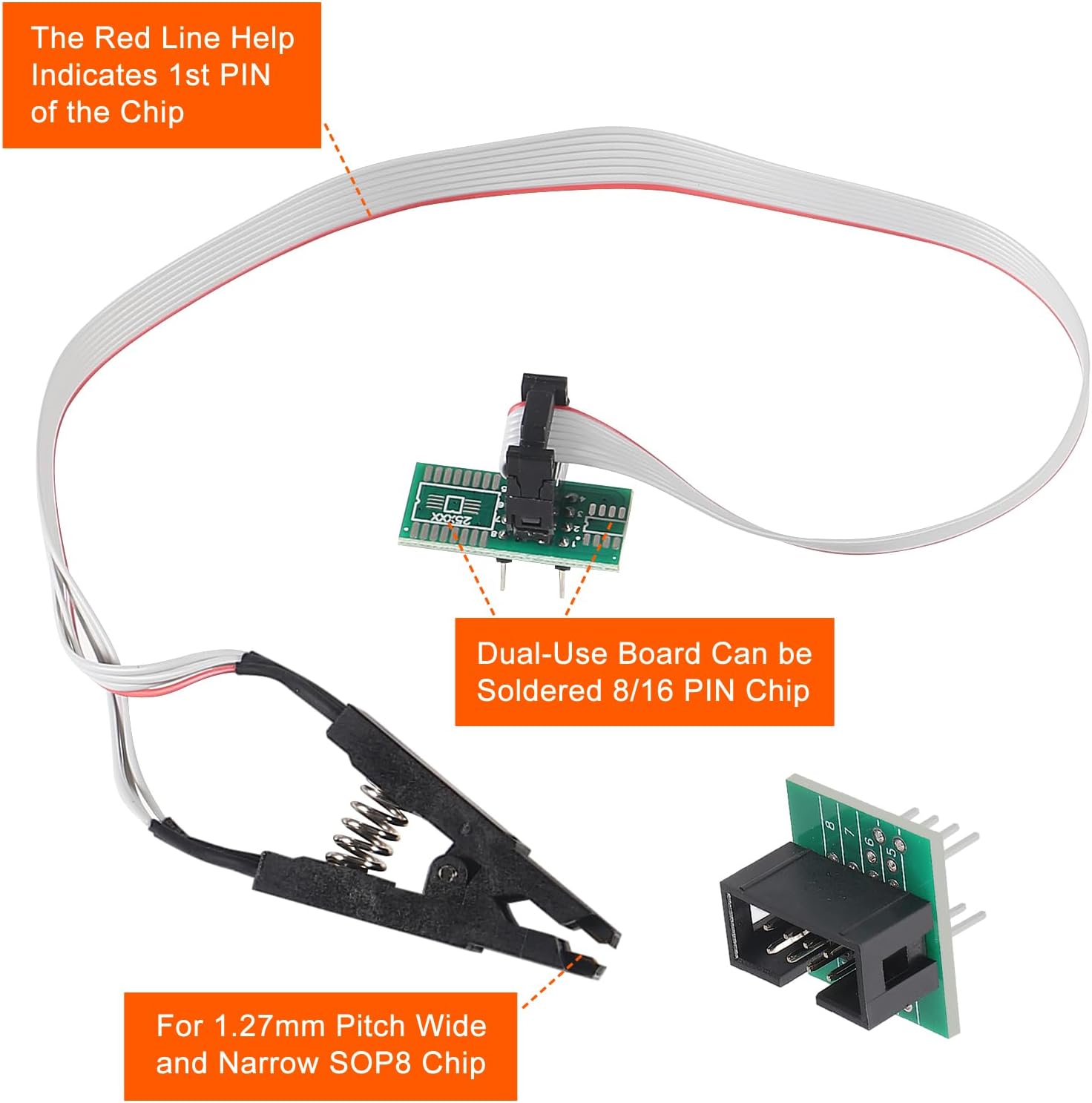
Figure 3: Connecting the SOIC8 SOP8 Test Clip, showing Pin 1 indication.
Method B: Using SOP8 to DIP8 Adapters (Out-of-Circuit Programming)
This method requires desoldering the chip from the board.
- Carefully desolder the SOP8 chip from its circuit board.
- Insert the desoldered SOP8 chip into the appropriate SOP8 to DIP8 adapter (150mil for narrow body, 200-208mil for wide body). Ensure correct orientation, matching Pin 1 on the chip to Pin 1 on the adapter.
- Insert the adapter with the chip into the ZIF socket of the CH341A programmer. Close the ZIF socket lever to secure the chip.
Method C: Using the Dual-Use Board (Soldering)
For chips that are difficult to clip or for permanent programming setups.
- Solder the 8-pin or 16-pin chip onto the dual-use board, ensuring correct pin alignment.
- Connect the dual-use board to the CH341A programmer using appropriate pin headers or cables.

Figure 4: Typical setup with the CH341A programmer and test clip.
Operating Instructions
The CH341A programmer is primarily used with dedicated programming software on your computer. The general workflow involves identifying the chip, reading its contents, erasing, programming new data, and verifying the operation.
General Programming Workflow
- Launch Software: Open the CH341A programming software on your computer.
- Detect Chip: In the software, select the correct chip manufacturer and model, or use the "Detect" function if available. Ensure the chip is correctly connected.
- Read Chip: Click the "Read" button to read the current data from the chip. It is highly recommended to save this data as a backup file before any erase or write operations.
- Erase Chip: If you intend to write new data, click the "Erase" button to clear the existing contents of the chip.
- Load Data: Load the desired firmware or data file (e.g., .bin, .hex) into the programming software.
- Program Chip: Click the "Program" or "Write" button to write the loaded data to the chip.
- Verify Chip: After programming, click the "Verify" button to compare the data on the chip with the loaded file, ensuring a successful write operation.

Figure 5: Core functions of the CH341A programmer: Backup, Erase, Burn, and Verify.
Supported Chip Series
The CH341A programmer supports most 24 Series (I2C EEPROM), 25 Series (SPI Flash EEPROM), and 93 Series (Microwire EEPROM) chips in SOP8 and SOP16 packages. Please consult the software's chip list for specific supported models.
Important Note: Due to the characteristics of the CH341A chip, some specific chips, such as the ESMT SST class 25 series, may only be readable and cannot be written to. Always check compatibility with your specific chip model.
Maintenance
Proper maintenance ensures the longevity and reliable operation of your programmer kit:
- Cleaning: Use a soft, dry cloth to clean the programmer and accessories. Avoid using liquid cleaners or solvents. For stubborn residue on pins or contacts, use isopropyl alcohol and a non-abrasive brush, ensuring components are completely dry before use.
- Storage: Store the kit in a cool, dry place, away from direct sunlight and dust. Keep the test clip and adapters in their protective packaging or a dedicated storage box to prevent damage to the pins.
- Handling: Handle the test clip and adapters with care to avoid bending or breaking the delicate pins.
Troubleshooting
If you encounter issues during programming, consider the following troubleshooting steps:
- Programmer Not Detected:
- Ensure drivers are correctly installed.
- Try a different USB port or computer.
- Check the USB cable for damage.
- Chip Not Detected / Read/Write Errors:
- Connection: This is the most common issue. Double-check that the test clip or adapter is correctly aligned and making firm contact with all chip pins. The red line on the clip cable indicates Pin 1.
- In-Circuit Programming: If using the test clip, ensure the target board is completely powered off and any peripheral circuits that might interfere with the chip's operation are disconnected or isolated. Some chips are affected by peripheral circuits and cannot be clipped directly.
- Chip Orientation: Verify the chip's orientation in the ZIF socket or adapter. Pin 1 must match.
- Chip Compatibility: Confirm that your specific chip model is supported by the CH341A programmer and the software version you are using. Remember that some chips (e.g., ESMT SST 25 series) may only support read operations.
- Power Supply: Ensure the USB port provides sufficient power. Try a powered USB hub if issues persist.
- Software Settings: Ensure the correct chip type is selected in the programming software.
- Programming Fails / Verification Errors:
- Ensure the chip was properly erased before programming.
- Verify the integrity of the firmware file you are attempting to write.
- Check for loose connections during the programming process.
Specifications
| Feature | Specification |
|---|---|
| Brand | ACEIRMC |
| Model Number | 2019042910503 |
| Hardware Interface | USB |
| Compatible Devices | Personal Computer |
| Supported Operating Systems | Windows, macOS, Linux |
| Supported Chip Series | 24CXX, 25CXX, 93CXX EEPROM/Flash BIOS |
| Clip Type | SOIC8 SOP8 Test Clip (1.27mm pitch) |
| Fuse | 500mA Self-Recovery Fuse |
| Crystal Oscillator | 12M |
Warranty and Support
For warranty information, technical support, or service inquiries, please contact your retailer or the manufacturer directly. Keep your purchase receipt as proof of purchase.