Introduction
This manual provides detailed instructions for assembling and operating your Icstation 3D Christmas Tree Soldering Kit. This kit is designed to enhance electronics knowledge and soldering skills, making it an ideal project for STEM education and hobbyists aged 15 and above. Upon successful assembly, the kit transforms into a decorative 3D Christmas tree with flashing RGB LED lights.

Image: Five fully assembled Icstation 3D Christmas Tree Soldering Kits, demonstrating the final appearance of the product.
Safety Information
Please read and understand all safety precautions before beginning assembly. This kit involves soldering, which requires careful handling of hot tools and electrical components.
- Age Recommendation: This kit is recommended for individuals 15 years and older. Younger users should have direct adult supervision.
- Eye Protection: Always wear safety glasses to protect your eyes from solder splatter and fumes.
- Ventilation: Work in a well-ventilated area to avoid inhaling solder fumes. Consider using a fume extractor.
- Hot Tools: Soldering irons become extremely hot. Handle with care and always place the iron in a suitable stand when not in use. Avoid touching the hot tip.
- Electrical Safety: Ensure your workspace is dry. Do not touch live electrical components.
- Component Handling: Some electronic components can be sensitive to static electricity. Handle them by their bodies, not their leads.
Package Contents
Verify that all components listed below are present in your kit before starting assembly. If any parts are missing or damaged, please contact customer support.
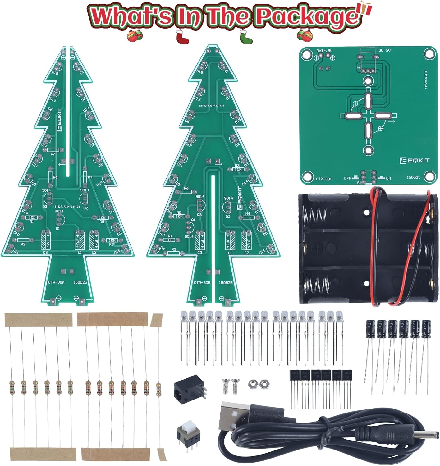
Image: All components included in the Icstation 3D Christmas Tree Soldering Kit, laid out for inspection.
Component List:
- 2 x Tree-shaped PCB boards (CTR-30A, CTR-30B)
- 1 x Base PCB board (CTR-30C)
- 1 x 3xAA Battery Holder
- 1 x USB Power Cable
- 36 x RGB LED Diodes
- Various Resistors (e.g., 1KΩ, 10KΩ, 220Ω, 470Ω)
- Various Capacitors (e.g., 100uF, 104)
- Transistors (e.g., S9014)
- Power Socket
- Switch
- Small Screws and Nuts
Setup and Assembly
Assembly of the 3D Christmas Tree Soldering Kit requires basic soldering tools, which are not included in the package. You will need a soldering iron, solder wire, and potentially desoldering braid or pump, and wire cutters.
Assembly Steps:
- Prepare Your Workspace: Ensure your soldering area is clean, well-lit, and well-ventilated. Have all necessary tools ready.
- Identify Components: The PCB boards have clear markings for each component (e.g., R1, C2, D3). Match the physical components to their designated spots on the PCB. Refer to the detailed English user manual (PDF) available for download on the product page for schematics and component values.
- Solder Resistors and Capacitors: Begin by soldering the smaller components like resistors and capacitors onto the tree-shaped PCB boards (CTR-30A and CTR-30B). Pay attention to the orientation of polarized capacitors if applicable.
- Solder Transistors: Solder the transistors onto the PCB boards. Ensure they are oriented correctly according to the markings on the board.
- Solder LEDs: This is a critical step. Each RGB LED diode has a positive (longer leg) and negative (shorter leg) lead. Insert the LEDs into the PCB holes, ensuring the longer leg aligns with the positive (+) marking on the board. Solder them securely. There are 36 RGB LED diodes in total.
- Assemble Tree Boards: Once all components are soldered onto the two tree-shaped PCBs, carefully interlock them to form the 3D tree structure.
- Solder Tree to Base: Solder the assembled 3D tree structure onto the base PCB (CTR-30C). Ensure a strong, stable connection.
- Solder Power Components: Solder the power socket, switch, and battery holder wires to the base PCB as indicated by the markings.
- Final Inspection: Before applying power, carefully inspect all solder joints for cold joints, bridges, or poor connections. Ensure all components are correctly oriented.

Image: A user engaged in the soldering process, illustrating the hands-on nature of the kit assembly.
For detailed schematics and step-by-step visual guides, please refer to the official PDF instruction manual. You can often find a link to download this manual on the product's online listing page.
Operating Instructions
Once assembled, your 3D Christmas Tree Soldering Kit is ready for operation.
Powering the Device:
The kit supports two power modes:
- 3 x AA Batteries: Insert three AA batteries (not included) into the provided battery holder. Connect the battery holder to the designated port on the base PCB.
- USB Power Adapter: Use the included USB cable to connect the kit to a DC 4.5V-5V USB power adapter (e.g., a phone charger, power bank, or computer USB port).

Image: Illustration of the two power supply methods: via USB cable or 3xAA batteries.
Light Functionality:
After connecting power and flipping the switch to the 'ON' position, the 36 RGB LED diodes will begin to flash, creating a bright, colorful, and dynamic light display. The LEDs cycle through various colors and patterns automatically.

Image: The assembled Christmas tree kit displaying its vibrant 7-color flashing LED lights.
Maintenance
The Icstation 3D Christmas Tree Soldering Kit requires minimal maintenance to ensure its longevity and performance.
- Cleaning: Use a soft, dry cloth to gently wipe the PCB and LEDs to remove dust. Avoid using liquids or abrasive cleaners.
- Storage: When not in use, store the assembled tree in a dry, cool place away from direct sunlight and excessive humidity.
- Battery Care: If using batteries, remove them if the device will not be used for an extended period to prevent leakage.
Troubleshooting
If you encounter issues with your assembled Christmas tree kit, refer to the following common troubleshooting steps:
| Problem | Possible Cause / Solution |
|---|---|
| Some or all LEDs do not light up. |
|
| Tree does not power on. |
|
| Lights are dim or flicker inconsistently. |
|
Specifications
| Feature | Detail |
|---|---|
| Product Dimensions (Assembled) | Approximately 1.96 x 1.57 x 0.78 inches (5 x 4 x 2 cm) |
| Item Weight | 10.5 ounces (approx. 298 grams) |
| Power Supply | DC 4.5V-5V (3 x AA batteries or USB power adapter) |
| LED Type | RGB LED Diodes (36 PCS) |
| Recommended Age | 15 years and up |
| Model Number | 13484 |

Image: Dimensional specifications of the assembled Christmas tree kit and its USB cable.
Support
For further assistance, technical inquiries, or if you encounter issues not covered in this manual, please contact the Icstation customer service team. A responsive service team is available to provide professional help and support.
You may also find additional resources and a downloadable PDF user manual on the product's official listing page or the Icstation brand store on Amazon.