1. Introduction
The BSIDE ZT-M1 is an advanced auto/manual ranging digital multimeter designed for precise electrical measurements. It features a 3-line triple display with 8000 counts, offering clear and comprehensive readings. This device is capable of performing battery tests, voltage measurements, VFC (Variable Frequency Control) measurements, and generating square wave outputs. Its robust design and multiple functions make it suitable for various electrical testing applications.
Key features include True RMS measurement, data hold, backlight, low battery indication, and auto power-off for energy efficiency. It supports both manual and automatic measurement modes, providing flexibility for different testing scenarios.
2. Safety Information
Always observe safety precautions when using the multimeter. Incorrect use can lead to electric shock, injury, or damage to the meter or equipment under test. Read all safety information carefully before operation.
- Do not exceed the maximum input values specified for each function.
- Ensure test leads are in good condition and properly connected before making measurements.
- Do not use the meter if it appears damaged or if the protective case is removed.
- Exercise caution when working with voltages above 30V AC RMS, 42V peak, or 60V DC, as these pose a shock hazard.
- Replace batteries when the low battery indicator appears to ensure accurate readings.
3. Setup
3.1 Battery Installation
The BSIDE ZT-M1 is battery-powered. To install or replace batteries, locate the battery compartment cover on the back of the device. Use a screwdriver to open the compartment, insert the required batteries (typically AA or AAA, refer to the compartment label for exact type and polarity), and securely close the cover.
3.2 Connecting Test Leads
Insert the red test lead into the 'VΩmA' or 'A' input jack, depending on the measurement function. Insert the black test lead into the 'COM' (common) input jack. Ensure a firm connection for accurate readings and safety.
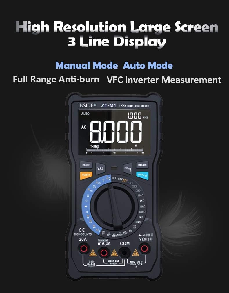
Image: The multimeter's rotary dial, illustrating the selection between Auto Mode (blue section) and Manual Mode (red section) for various testing functions.
4. Operating Instructions
4.1 Power On/Off
Turn the rotary switch from the 'OFF' position to any desired measurement function to power on the multimeter. To power off, turn the rotary switch back to the 'OFF' position. The meter also features an auto power-off function to conserve battery life after a period of inactivity.
4.2 Display and Modes
The ZT-M1 features a high-resolution 3-line triple display, showing primary measurement, secondary information, and an analog bar graph. It supports both Manual Mode and Auto Mode. Use the 'SELECT' button to switch between different sub-functions within a rotary switch position (e.g., AC/DC voltage, resistance/continuity).

Image: The multimeter's large, high-resolution 3-line display, showing an AC voltage reading of 8.000V and other measurement details.
4.3 Measurement Functions
- DC/AC Voltage (V/mV): Select the 'V' or 'mV' position on the rotary switch. Connect test leads in parallel to the circuit.
- DC/AC Current (A/mA): Select the 'A' or 'mA' position. Connect test leads in series with the circuit. Ensure correct input jack usage (8A/20A or 800mA).
- Resistance (Ω): Select the 'Ω' position. Connect test leads across the component.
- Capacitance (F): Select the 'F' position. Connect test leads across the capacitor.
- Frequency (Hz) / Duty Cycle (%): Select the 'Hz/%' position. Connect test leads to the signal source.
- Temperature (°C/°F): Select the 'TEMP' position. Use the included thermocouple probe.
- Diode Test: Select the diode symbol position. Connect test leads across the diode.
- Continuity Test: Select the continuity symbol position. Connect test leads across the circuit. An audible beep indicates continuity.
- Battery Test: Select the '1.5V B' or '9V B' or '12V B' position to test common battery voltages.
- VFC (Variable Frequency Control) Measurement: This function allows measurement of the output voltage of inverters. Select the 'VFC' position on the rotary switch.

Image: Top panel shows the 3-line display indicating temperature in Celsius and Fahrenheit. Bottom panel shows the multimeter measuring the output voltage of an inverter using the VFC function.
4.4 Special Features
- Data Hold: Press the 'HOLD' button to freeze the current reading on the display. Press again to release.
- Backlight: Press the backlight button to illuminate the display for use in low-light conditions.
- Flashlight: The integrated flashlight provides illumination for testing in dark environments.
- Square Wave Output: The meter can generate a square wave output from 50Hz to 5000Hz.
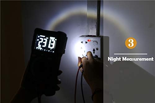
Image: The multimeter's integrated flashlight illuminating a power outlet during a measurement in a dark environment.
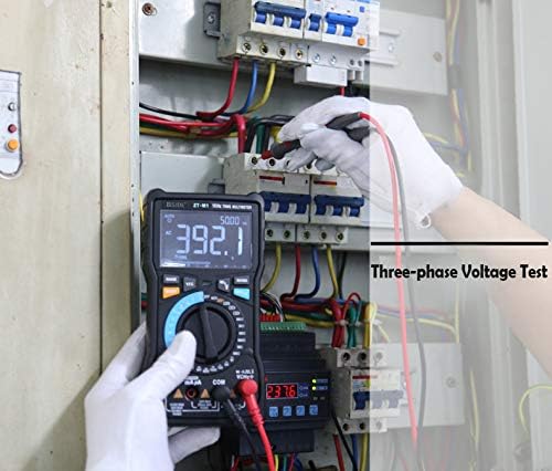
Image: A user performing a three-phase voltage test within an electrical panel using the BSIDE ZT-M1 multimeter.
5. Maintenance
5.1 Cleaning
Wipe the meter's casing with a damp cloth and mild detergent. Do not use abrasives or solvents. Ensure the meter is powered off and test leads are disconnected before cleaning.
5.2 Battery Replacement
Replace batteries promptly when the low battery indicator appears on the display to maintain measurement accuracy. Refer to section 3.1 for battery installation instructions.
5.3 Probe Care
Inspect test leads for any damage (cuts, cracks) before each use. Replace damaged leads immediately. The multimeter includes a back probe holder for safe storage and transport of probes.

Image: A collage showing the multimeter's back probe holder for safe storage, the integrated flashlight, and the protective case designed for shock and bump protection.
6. Troubleshooting
- No Display: Check battery installation and ensure batteries are charged.
- Inaccurate Readings: Verify correct function selection, proper test lead connection, and ensure batteries are not low.
- No Continuity Beep: Ensure the circuit is de-energized and the continuity function is selected. Check test leads for damage.
- Meter Does Not Respond: Turn the meter off and then on again. If the issue persists, replace batteries.
7. Specifications
| Feature | Specification |
|---|---|
| Display | 8000 counts, 3-line Triple Display |
| Ranging | Auto/Manual |
| Material | ABS/PVC |
| Update Rate | 3 times/second |
| True RMS | Yes |
| Data Hold | Yes |
| Backlight | Yes |
| Battery Test | Yes (1.5V, 9V, 12V) |
| V.F.C (Variable Frequency Control) | Yes |
| Low Battery Indication | Yes |
| Auto Power Off | Yes |
| Temperature Measurement | -20°C to 1000°C (-4°F to 1832°F) (2.5%+5) |
| Resistance Range | 0.1Ω - 80MΩ |
| Capacitance Range | 0.001nF - 100mF |
| Measurement Mode | Manual Mode + Automatic Mode |
| DC Voltage (V) | 800.0mV/8.000V/80.00V/800.0V/1000V (0.5%+3) |
| AC Voltage (V) | 800.0mV/8.000V/80.00V/800.0V/750V (1.0%+3) |
| DC Current (A) | 8.000A/20.00A (1.2%+3) |
| DC Current (mA) | 8.000mA/80.00mA/800.0mA (1.2%+3) |
| AC Current (A) | 8.000A/20.00A (1.5%+3) |
| AC Current (mA) | 8.000mA/80.00mA/800.0mA (1.5%+3) |
| Frequency | 9.999Hz/99.99Hz/999.9Hz (0.1%+2) |
| Duty Cycle | 1%~99% (0.1%+2) |
| Diode Test | Yes |
| Continuity Test | Yes |
| Square Wave Output | 50Hz~5000Hz |


