1. Introduction
This manual provides essential information for the safe and efficient operation of your Boiler-m8 25-10 A Rated Light Commercial Circulating Pump. Please read these instructions carefully before installation and use, and retain them for future reference.
The Boiler-m8 25-10 circulating pump is engineered for central heating systems, boilers, and radiators. It features an automatic variable speed motor, ensuring low energy consumption and high efficiency. Designed to accommodate larger domestic and semi-commercial systems, this model offers a 10-meter head capacity.
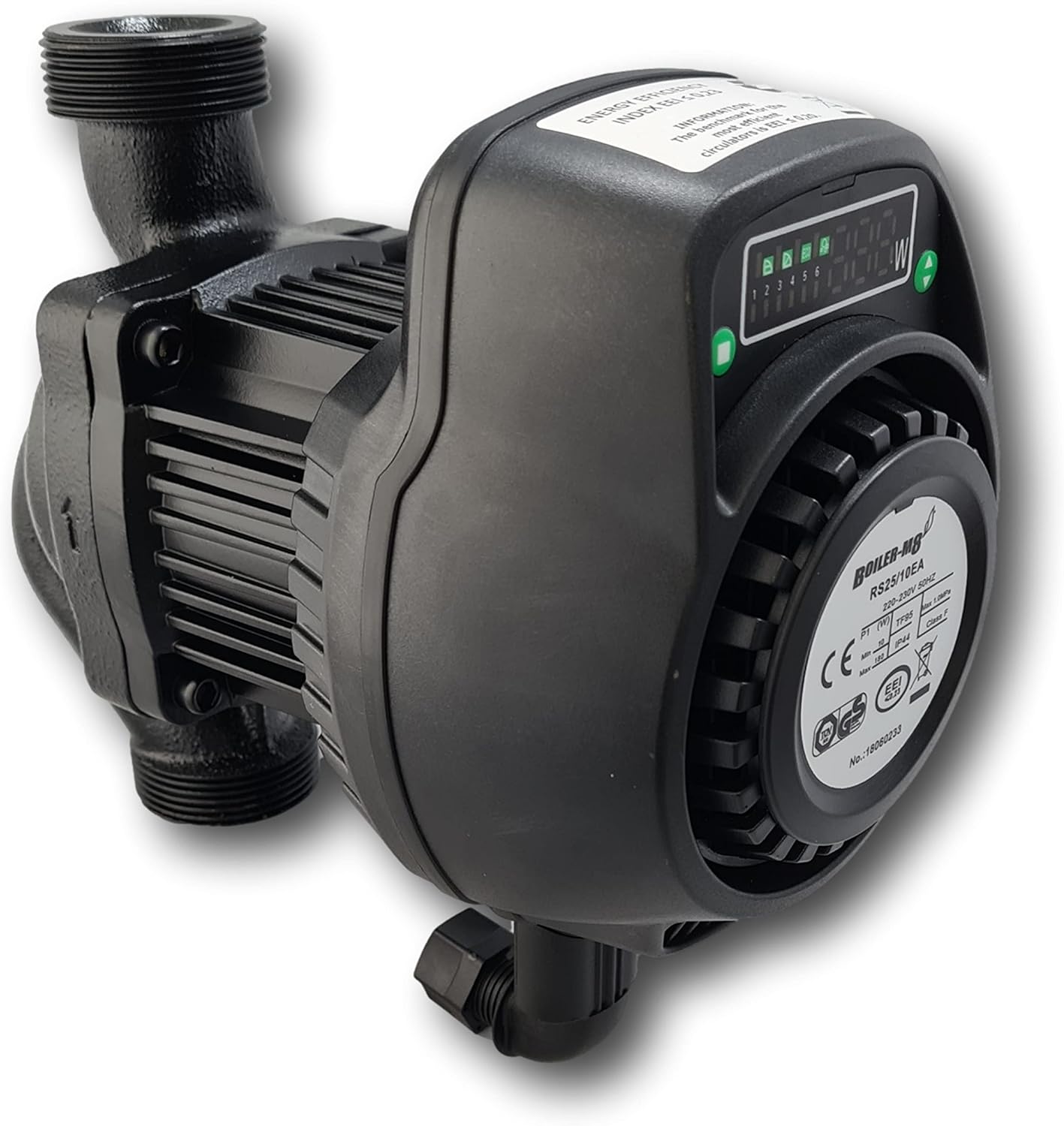
Figure 1: Boiler-m8 25-10 A Rated Light Commercial Circulating Pump. This image shows the main unit of the circulating pump, highlighting its compact design and robust construction.
Key Features:
- Automatic variable speed motor with fixed speed overrides.
- Low energy consumption and high efficiency ('A' Rated).
- 10-meter pump head suitable for larger systems.
- ErP Compliant.
- IP44 protection rating.
- 5-year manufacturer's warranty.
2. Safety Information
WARNING: Improper installation, operation, or maintenance can cause serious injury or property damage. Always follow these safety guidelines.
- Electrical Safety: Ensure the power supply is disconnected before any installation, maintenance, or repair work. All electrical connections must be performed by a qualified electrician in accordance with local regulations.
- Water Temperature: The pump handles water up to 95°C. Exercise extreme caution to avoid burns when working with hot water systems.
- Pressure: The system operates under pressure. Depressurize the system before opening any connections.
- Installation: The pump must be installed in a dry, well-ventilated area, protected from frost and direct sunlight.
- Children: Keep children away from the installation area and operating pump.
3. Package Contents
Verify that all items are present and undamaged upon unpacking:
- 1 x Boiler-m8 25-10 A Rated Light Commercial Circulating Pump
- 2 x Gaskets (for connection)
- 1 x Electrical connection elbow with terminal block and screws

Figure 2: Connection parts including the electrical elbow and gaskets. These components are essential for securing the pump to the heating system and connecting it to power.
4. Installation and Setup
Installation should be carried out by a qualified professional. Ensure the heating system is drained and depressurized before beginning installation.
4.1 Mechanical Installation
- Position the pump in the heating system pipework, ensuring the flow direction arrow on the pump body matches the system's flow.
- The pump is designed for a connection distance of 180mm.
- Use the provided G 1½" BSP connections and gaskets to secure the pump to the pipework. Ensure a watertight seal without overtightening.

Figure 3: An alternative view of the Boiler-m8 pump, showing its inlet and outlet connections. This perspective helps in understanding how the pump integrates into a heating system's pipework.
4.2 Electrical Connection
WARNING: Electrical work must be performed by a qualified electrician.
- Ensure the main power supply to the heating system is switched off at the circuit breaker.
- Open the terminal box cover on the pump.
- Connect the power cable (230-240V, 50Hz) to the terminal block (L, N, Earth) using the provided electrical connection elbow and screws. Ensure proper grounding.
- Securely close the terminal box cover, ensuring no wires are pinched.
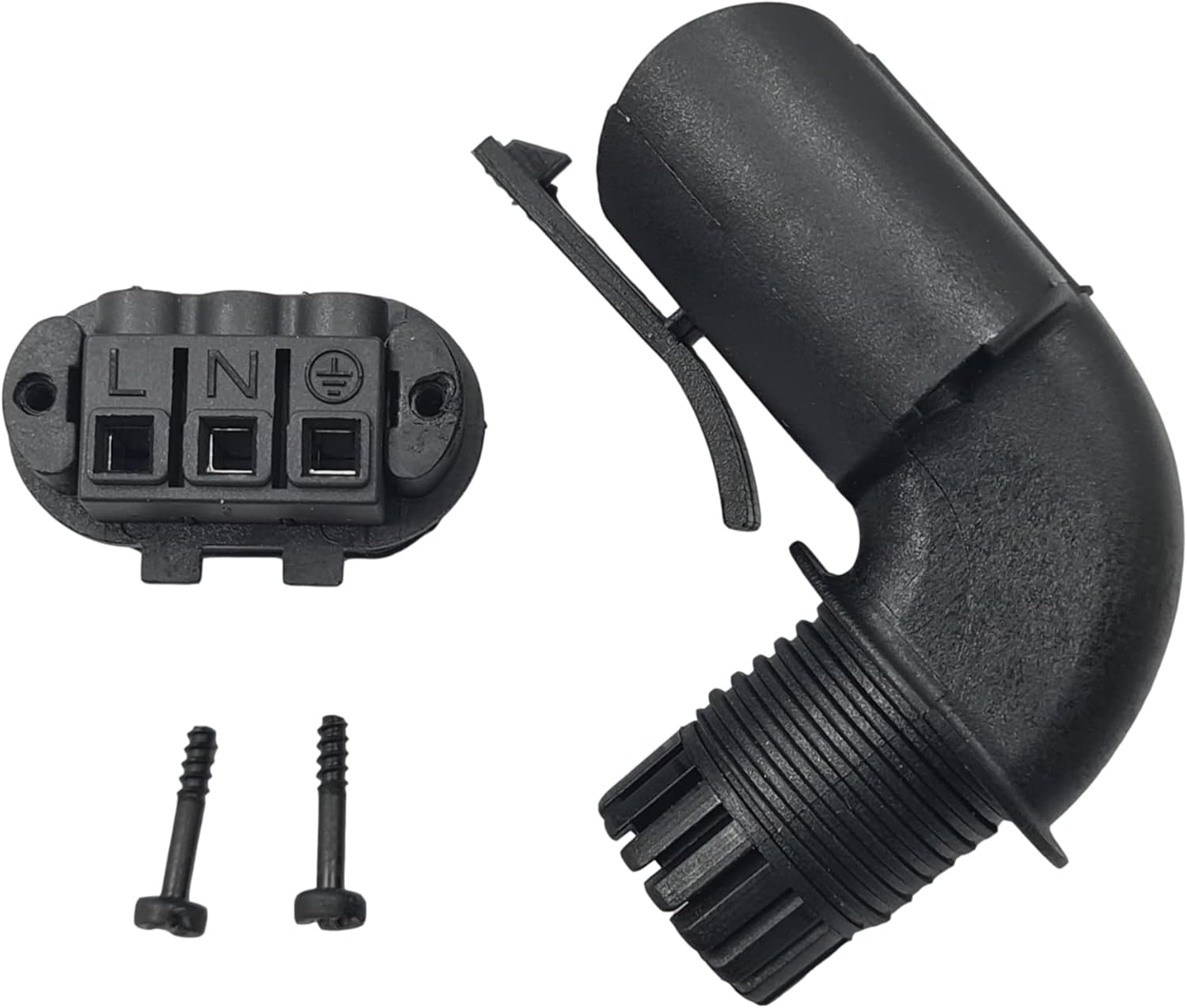
Figure 4: Close-up of the electrical terminal block and connection elbow. This image details the L (Live), N (Neutral), and Earth connections, crucial for safe electrical installation.
4.3 System Filling and Venting
- After mechanical and electrical installation, refill the heating system according to the boiler manufacturer's instructions.
- Bleed all air from the system, including the pump itself, using any available vent screws or the pump's integrated vent function (if applicable).
- Check for leaks at all connections.
5. Operating Instructions
The Boiler-m8 25-10 pump features a control panel for selecting operating modes.

Figure 5: Detailed view of the pump's control panel and display. This shows the digital readout for power consumption and indicators for selected operating modes.
5.1 Control Panel Overview
The control panel typically includes:
- Digital Display: Shows current power consumption (W) and selected mode.
- Mode Selection Buttons: Used to cycle through different operating modes.
- Indicators: LEDs or icons to show the active mode (e.g., Eco, Proportional, Constant Pressure, Fixed Speeds).
5.2 Operating Modes
The pump offers both automatic and fixed speed modes:
- Automatic Modes:
- Eco Mode: Optimizes energy consumption based on system demand.
- Proportional Pressure Mode: Adjusts pump performance proportionally to system pressure changes.
- Constant Pressure Mode: Maintains a constant pressure differential regardless of flow rate.
- Fixed Speed Modes: Six adjustable fixed power modes are available, allowing manual selection of a constant operating speed.
To select a mode, press the mode selection button(s) on the control panel until the desired mode is indicated on the display.
5.3 Vent Function
The pump may include a vent function to assist in removing air from the pump housing. Consult the specific instructions on the control panel or product label for activating this feature.
6. Maintenance
Regular maintenance ensures optimal performance and longevity of your circulating pump.
- Annual Inspection: It is recommended to have a qualified technician inspect the pump and heating system annually.
- Cleaning: Keep the exterior of the pump clean and free from dust and debris. Do not use abrasive cleaners or solvents.
- System Water Quality: Ensure the heating system water is treated to prevent corrosion and scale buildup, which can affect pump performance.
- Frost Protection: If the pump is installed in an area susceptible to freezing, ensure adequate frost protection measures are in place or drain the system during periods of inactivity.
7. Troubleshooting
Before attempting any repairs, always disconnect the power supply to the pump.
| Problem | Possible Cause | Solution |
|---|---|---|
| Pump not running | No power supply; Air in pump; Motor seized. | Check power connections and circuit breaker; Vent the pump; Contact a qualified technician. |
| Pump making noise | Air in system; Cavitation; Foreign objects in pump. | Vent the system thoroughly; Check system pressure; Contact a qualified technician. |
| Insufficient flow/pressure | Air in system; Blockage; Incorrect mode selection. | Vent the system; Check for blockages in pipes/filters; Select a higher performance mode. |
| Error Code E06 | Internal fault; Electrical issue. | Disconnect power, wait a few minutes, then reconnect. If the error persists, contact Boiler-m8 support or a qualified technician. |
8. Technical Specifications
| Brand | Boiler-m8 |
| Model | 25-10 |
| Part Number | 155-0009 |
| Product Type | Light Commercial Circulating Pump |
| Voltage/Frequency | 230-240V / 50Hz |
| Inlet/Outlet Thread | G 1½" BSP |
| Connection Distance | 180mm |
| Max Flow | 125 L/min |
| Max Head | 10m |
| Max Power | 130W |
| Temperature Range | Up to 95°C |
| Insulation Class | H |
| EEI (Energy Efficiency Index) | ≤ 0.23 |
| Protection Rating | IP44 |
| Material | Cast iron |
| Item Weight | 3.62 Kilograms |
9. Warranty and Support
9.1 Manufacturer's Warranty
The Boiler-m8 25-10 A Rated Light Commercial Circulating Pump comes with a 5-year manufacturer's warranty from the date of purchase. This warranty covers defects in materials and workmanship under normal use and service.
The warranty does not cover damage resulting from improper installation, misuse, neglect, unauthorized modifications, or acts of nature. Please retain your proof of purchase for warranty claims.
9.2 Customer Support
For technical assistance, troubleshooting beyond this manual, or warranty claims, please contact your retailer or the Boiler-m8 customer support team. Have your product model number (25-10) and part number (155-0009) ready when contacting support.


