1. Introduction
The Diymore STC-3008 is a versatile digital temperature controller designed for precise temperature management in various applications. It features dual heating and cooling functions, allowing for accurate temperature control by setting specific temperature values and difference thresholds. Equipped with two independent NTC waterproof sensors, it can monitor and control two separate environments simultaneously.
Key Features:
- Dual heating and cooling functions for comprehensive temperature control.
- Temperature calibration for enhanced accuracy.
- Refrigerant output delay control to protect compressors.
- Automatic over-temperature alarm for safety.
- Two clear digital displays and two waterproof NTC sensors.
- Wide temperature measurement range: -55 ℃ to 120 ℃.
- Suitable for household freezers, water tanks, refrigerators, aquariums, home brewing, chicken incubators, and laboratory temperature-controlled systems.

Figure 1.1: The STC-3008 Digital Temperature Controller, including the main unit, two NTC waterproof sensors, and the instruction manual, packaged in its retail box.
2. Safety Precautions
Please read and understand all safety instructions before installing or operating the STC-3008 temperature controller. Failure to follow these instructions may result in electric shock, fire, or damage to the device.
- Electrical Safety: Ensure the power supply matches the device's specifications (AC110-220V). All wiring should be performed by a qualified electrician. Disconnect power before making any connections or performing maintenance.
- Proper Wiring: Strictly distinguish the interface of the relay, sensor, and power supply. Ensure all connections are secure and correct to prevent short circuits or malfunctions.
- Sensor Placement: The sensor down-lead and power wire should be kept a proper distance apart to avoid interference.
- Environment: Do not expose the device to excessive moisture, dust, or extreme temperatures outside its operating range.
- Ventilation: Ensure adequate ventilation around the unit for effective heat dissipation.
- Intended Use: Use the controller only for its intended purpose of temperature regulation. Do not modify the device.
3. Product Components and Identification
The STC-3008 temperature controller consists of the main unit and two NTC waterproof sensors. Below is a detailed description of its key components:

Figure 3.1: Detailed view of the STC-3008's internal and external components.
- Precision Component: Scientific arrangement ensures optimal performance and accuracy.
- Sealed Terminal Block: Provides strong and safe electrical conductivity for reliable connections.
- Anti-breakdown Capacitor: Integrated into the maximum protection circuit for enhanced durability.
- Clear Display: Features two bright digital displays (red for OUT1, blue for OUT2) for clear and accurate temperature readings.
- Durable Buttons: Designed for longevity, tested for over 200,000 presses.
- NTC Waterproof Sensors: Two included sensors, each 1 meter in length, for accurate temperature detection in various environments.
- Cooling Grid Design: Integrated into the casing for effective heat dissipation, ensuring stable operation.
4. Technical Specifications

Figure 4.1: Dimensions of the STC-3008 controller and sensor.
| Parameter | Value |
|---|---|
| Model | STC-3008 |
| Power Supply | AC110-220V, 50/60 Hz |
| Temperature Measurement Range | -55 ℃ ~ 120 ℃ (-67 °F ~ 248 °F) |
| Resolution | 0.1 °C |
| Sensor Type | NTC (10K/3435) waterproof sensor |
| Sensor Length | 1 meter (including probe) |
| Output | Relay output (10A/220VAC) |
| Product Dimensions | 75(L) x 34.5(W) x 85(D) mm |
| Front Panel Size | 75(L) x 34.5(W) mm |
| Mounting Hole Size | 71(L) x 29(W) mm |
| Weight | 140 grams |
| Display Type | LCD or LED |
| Operating Temperature | Up to 120 °C |
5. Installation and Wiring
The STC-3008 is designed for panel mounting. Ensure the mounting hole dimensions match the product specifications (71mm x 29mm). Proper wiring is crucial for safe and correct operation.
Wiring Diagram:

Figure 5.1: STC-3008 Wiring Diagram.
Important Note: There is no voltage output from the output terminal of the thermostat. The device needs to be connected to an external power supply for the load (heating/cooling device) to function.
Connection 1: Independent Power Supply for Load
- Connect the main power supply (110V/220VAC) to terminals 1 and 2 (Power Supply).
- Connect Sensor 1 to terminals 3 and 4.
- Connect Sensor 2 to terminals 5 and 6.
- For Output 1 (OUT1), connect the load (e.g., heater/cooler) to terminals 7 and 8. Provide an independent power supply (110V/220VAC) to this load.
- For Output 2 (OUT2), connect the load to terminals 9 and 10. Provide an independent power supply (110V/220VAC) to this load.
Connection 2: Same Power Supply for Load
- Connect the main power supply (110V/220VAC) to terminals 1 and 2 (Power Supply).
- Connect Sensor 1 to terminals 3 and 4.
- Connect Sensor 2 to terminals 5 and 6.
- For Output 1 (OUT1), connect one side of the load to terminal 7 and the other side to the live wire of the main power supply.
- For Output 2 (OUT2), connect one side of the load to terminal 9 and the other side to the live wire of the main power supply.
- Ensure the neutral wire of the main power supply is connected to the neutral side of both loads.
Always ensure that the sensor down-lead and power wire are kept a proper distance to avoid electrical interference.
6. Initial Setup and Parameter Settings
The STC-3008 allows for various parameter settings to customize its operation. The two displays show the current temperature readings from Sensor 1 (red) and Sensor 2 (blue).
Button Functions:
- SET Button: Press once to view the current set temperature. Press and hold for 3 seconds to enter parameter setting mode.
- UP (▲) Button: Increase value or navigate through parameters.
- DOWN (▼) Button: Decrease value or navigate through parameters.
Parameter Setting Mode:
To enter parameter setting mode, press and hold the SET button for 3 seconds. Use the UP and DOWN buttons to navigate between parameters (P0 to P8) and adjust their values. Press SET again to confirm a value and move to the next parameter, or wait 10 seconds for automatic exit.
| Parameter | Description | Range | Default |
|---|---|---|---|
| P0 | Heating/Cooling Mode (OUT1) | H (Heating) / C (Cooling) | C |
| P1 | Hysteresis (Temperature Difference) | 0.1 ~ 30.0 °C | 2.0 °C |
| P2 | Upper Temperature Limit (OUT1) | -55 ~ 120 °C | 120 °C |
| P3 | Lower Temperature Limit (OUT1) | -55 ~ 120 °C | -55 °C |
| P4 | Temperature Calibration (OUT1) | -10.0 ~ 10.0 °C | 0.0 °C |
| P5 | Delay Start Time (OUT1) | 0 ~ 10 minutes | 0 minutes |
| P6 | High Temperature Alarm (OUT1) | -55 ~ 120 °C | 120 °C |
| P7 | Heating/Cooling Mode (OUT2) | H (Heating) / C (Cooling) | C |
| P8 | Hysteresis (Temperature Difference) (OUT2) | 0.1 ~ 30.0 °C | 2.0 °C |
To restore factory settings, press and hold both the UP and DOWN buttons simultaneously for 3 seconds while in normal operating mode. The display will show "888" indicating successful reset.
7. Operating Instructions
Once the STC-3008 is correctly wired and powered on, it will display the current temperatures from both sensors. The controller operates based on the set parameters (P0-P8).
Setting the Target Temperature:
- Press the SET button once. The current set temperature for OUT1 will flash.
- Use the UP (▲) or DOWN (▼) buttons to adjust the desired target temperature.
- Press SET again to confirm the setting and exit, or wait 10 seconds for automatic exit.
Heating Mode (P0 = H):
In heating mode, the output (OUT1 or OUT2) will activate when the measured temperature falls below the set temperature minus the hysteresis (P1). It will deactivate when the temperature reaches or exceeds the set temperature.
Example: If Set Temp = 25°C and Hysteresis (P1) = 2°C, the heater will turn on when temperature drops to 23°C or below, and turn off when it reaches 25°C.
Cooling Mode (P0 = C):
In cooling mode, the output (OUT1 or OUT2) will activate when the measured temperature rises above the set temperature plus the hysteresis (P1). It will deactivate when the temperature reaches or falls below the set temperature.
Example: If Set Temp = 5°C and Hysteresis (P1) = 2°C, the cooler will turn on when temperature rises to 7°C or above, and turn off when it reaches 5°C.
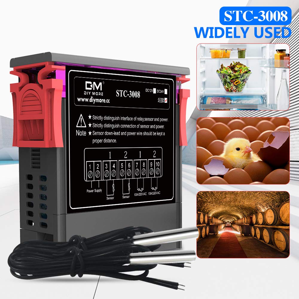
Figure 7.1: Common applications for the STC-3008 controller.
8. Maintenance
Regular maintenance ensures the longevity and optimal performance of your STC-3008 temperature controller.
- Cleaning: Disconnect power before cleaning. Use a soft, dry cloth to wipe the unit. Do not use abrasive cleaners or solvents.
- Sensor Inspection: Periodically check the NTC sensors for any signs of damage or corrosion. Ensure they are securely connected.
- Ventilation: Ensure the cooling grids on the side of the unit are free from dust and obstructions to maintain effective heat dissipation.
- Wiring Check: Occasionally inspect all wiring connections to ensure they remain tight and secure.
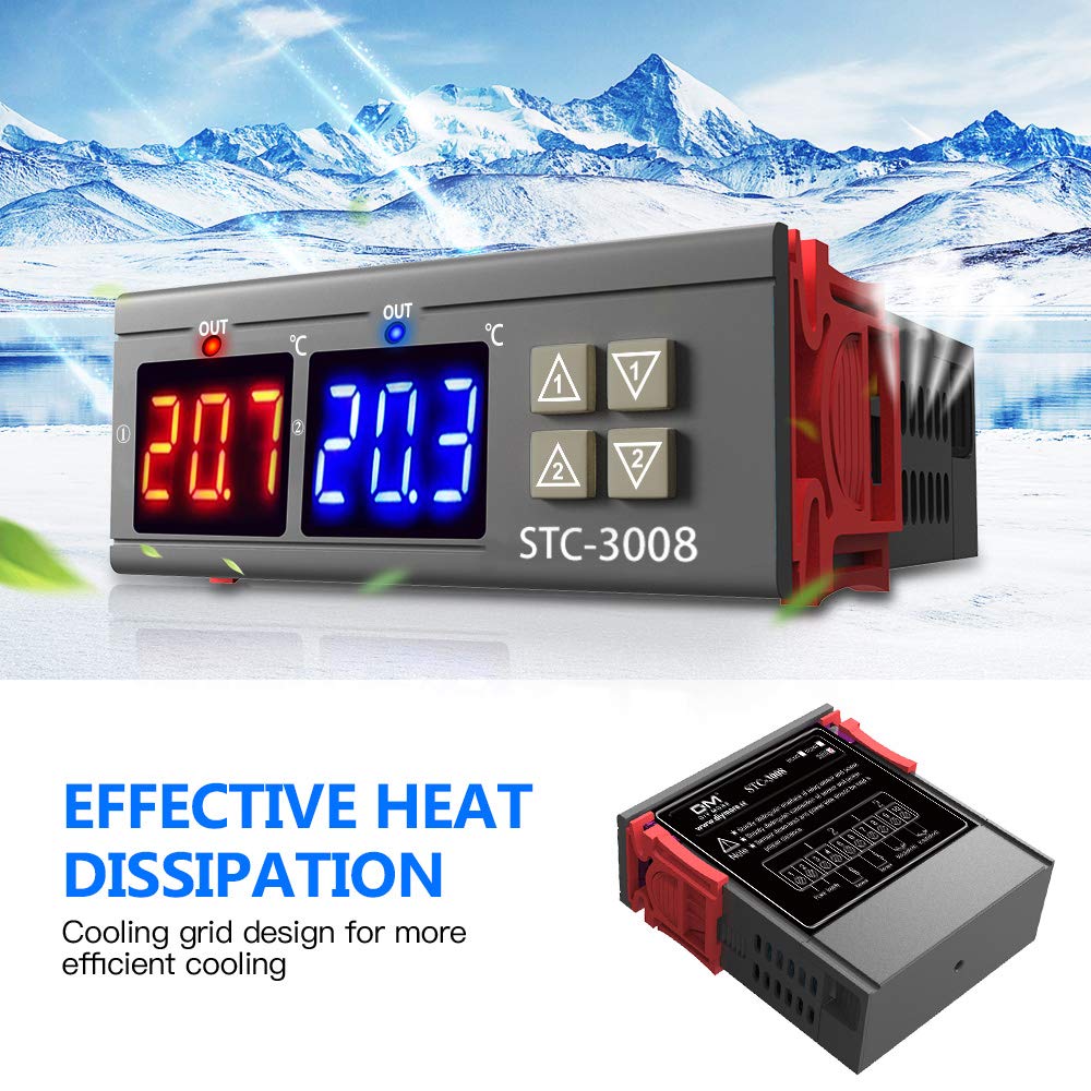
Figure 8.1: The STC-3008 features a cooling grid design for efficient heat dissipation.
9. Troubleshooting
If you encounter issues with your STC-3008, refer to the table below for common problems and their solutions.
| Problem | Possible Cause | Solution |
|---|---|---|
| Display shows "HHH" or "LLL" | Sensor error (open circuit or short circuit) or temperature exceeds range. | Check sensor connections. Replace sensor if damaged. Ensure temperature is within -55°C to 120°C. |
| Output not activating | Incorrect wiring, set temperature not met, delay start (P5) active, or load not powered. | Verify wiring according to diagram. Check set temperature and hysteresis. Wait for delay time to pass. Ensure external load has power. |
| Temperature reading inaccurate | Sensor calibration needed (P4) or faulty sensor. | Adjust P4 for temperature calibration. If issue persists, replace sensor. |
| Unit not powering on | No power supply or incorrect voltage. | Check power connections and ensure voltage is 110-220V AC. |
10. Warranty Information
Diymore products are manufactured with high quality standards. While specific warranty details are not provided in this manual, please refer to your purchase documentation or the seller's policy for warranty terms and conditions. Typically, electronic products come with a standard manufacturer's warranty against defects in materials and workmanship.
Keep your proof of purchase for any warranty claims.
11. Customer Support
For technical assistance, troubleshooting beyond this manual, or warranty inquiries, please contact Diymore customer service or the retailer from whom you purchased the product.
You can often find support information on the official Diymore website or through the Amazon seller page.
Diymore Official Store: Visit Diymore Store on Amazon
Your satisfaction is our goal. Do not hesitate to contact us if you have any questions.


