1. Introduction
This manual provides detailed instructions for the safe and effective operation of the AOPUTTRIVER AP-570T-APP Bluetooth Digital Clamp Multimeter. This device is designed for measuring AC/DC voltage, AC/DC current, resistance, capacitance, frequency, duty cycle, and temperature. It also features diode testing, continuity testing, and a data hold function. The integrated Bluetooth connectivity allows for remote monitoring and data logging via a dedicated mobile application.

Figure 1: AOPUTTRIVER AP-570T-APP Digital Clamp Multimeter. This image shows the front view of the multimeter, highlighting its display and rotary switch.
2. Safety Information
To ensure safe operation, please read and understand all safety warnings and operating instructions before using this instrument. Failure to observe these warnings can result in severe injury or death.
- Always adhere to local and national safety codes.
- Do not use the meter if it appears damaged or if the insulation on the test leads is compromised.
- Verify the meter's operation on a known voltage source before use.
- Do not apply more than the rated voltage, as marked on the meter, between the terminals or between any terminal and ground.
- Use caution when working with voltages above 30V AC RMS, 42V peak, or 60V DC. These voltages pose a shock hazard.
- Always disconnect power to the circuit and discharge all high-voltage capacitors before performing resistance, continuity, diode, or capacitance measurements.
- Keep fingers behind the finger guards on the test probes during measurements.
- Replace the battery immediately when the low battery indicator appears to ensure accurate readings.
- The device is rated IEC 61010-1, CAT IV 600 V, CAT III 1000 V, Class 2, with double insulation.
3. Product Features
The AOPUTTRIVER AP-570T-APP offers a range of features for comprehensive electrical testing:
- Digital Multimeter Functions: 4000 counts, optional auto/manual range for AC current. Auto range for DC current, AC/DC voltage, resistance, capacitance, frequency, and duty cycle. Backlit display, data hold, temperature (℃/℉), diode test, relative value, continuity test with audible alarm.
- Temperature Measurement: Measures temperature in Celsius (℃) and Fahrenheit (℉) with an included thermocouple probe, ranging from -20℃ to 1000℃.
- Bluetooth Connectivity: Connects to Android/iOS phones for remote control, monitoring, continuous testing, and data logging. Data can be saved in TXT or Excel formats.
- High Precision Clamp Meter: Offers 1A resolution for AC/DC current from 1A to 1000A, suitable for high and low current measurements. Jaw opening of 45mm.
- Durable Design: Engineered to withstand drops and harsh work site conditions, meeting IEC 61010-1 safety standards.
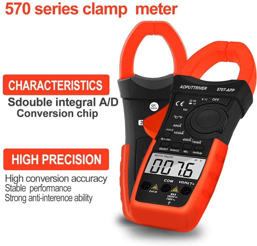
Figure 2: Key characteristics of the AP-570T-APP clamp meter, highlighting its double integral A/D conversion chip and high precision for stable performance.
4. Components and Controls
Familiarize yourself with the parts of your AP-570T-APP multimeter:
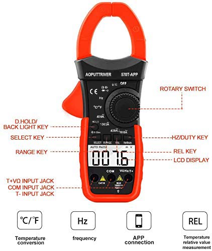
Figure 3: Diagram illustrating the main controls and input jacks of the AP-570T-APP multimeter.
- Rotary Switch: Used to select measurement functions (e.g., V~, V-, A~, A-, Ω, Hz, ℃/℉, Diode, Continuity).
- LCD Display: Shows measurement readings, units, and function indicators.
- D.HOLD / Backlight Key: Press briefly to hold the current reading; press and hold to activate/deactivate the backlight.
- SELECT Key: Toggles between different measurement modes within a function (e.g., AC/DC voltage, Diode/Continuity).
- RANGE Key: Switches between auto-ranging and manual-ranging modes.
- REL Key: Activates the relative measurement function.
- Hz/Duty Key: Selects frequency or duty cycle measurement.
- Input Jacks:
- COM: Common input jack for all measurements.
- VΩHzT+: Positive input jack for voltage, resistance, frequency, and temperature measurements.
- T-: Negative input jack for temperature measurements (used with thermocouple).
- Clamp Jaw: Used for non-contact AC/DC current measurement. Maximum opening: 45mm.

Figure 4: Close-up view of the current clamp jaw, showing its 45mm opening and the secure closure mechanism.
5. Setup
5.1 Battery Installation
The multimeter requires one 9V battery (included). To install or replace the battery:
- Ensure the multimeter is turned OFF.
- Locate the battery compartment cover on the back of the device.
- Use a small screwdriver (included) to loosen the screw securing the cover.
- Remove the cover.
- Connect the 9V battery to the battery clips, observing correct polarity.
- Place the battery into the compartment and replace the cover, securing it with the screw.
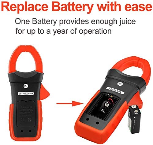
Figure 5: Illustration of how to access and replace the 9V battery in the AP-570T-APP multimeter.
5.2 Mobile App Connection (Bluetooth)
The AP-570T-APP can connect to your smartphone via Bluetooth for enhanced functionality.
- Download the "AP-570T-APP" application from your device's app store (Android/iOS).
- Ensure Bluetooth is enabled on your smartphone.
- Turn on the AOPUTTRIVER AP-570T-APP multimeter.
- Open the downloaded application on your phone.
- The app should automatically detect and connect to the multimeter. Follow any on-screen prompts if pairing is required.
- Once connected, you can view real-time measurements, log data, and control certain functions remotely.

Figure 6: The AP-570T-APP multimeter displayed alongside a smartphone showing its connected application interface, demonstrating remote monitoring capabilities.
6. Operating Instructions
Always ensure the meter is set to the correct function and range before making any measurements. Connect test leads to the appropriate input jacks.
6.1 AC/DC Voltage Measurement
- Insert the red test lead into the VΩHzT+ jack and the black test lead into the COM jack.
- Turn the rotary switch to the V~ (AC Voltage) or V- (DC Voltage) position.
- If measuring AC voltage, press the SELECT button to toggle between AC and DC if necessary (for combined V~ / V- position).
- Connect the test probes in parallel to the circuit or component under test.
- Read the voltage value on the LCD display.

Figure 7: Example of performing a DC current test using the clamp function on electrical wiring.
6.2 AC/DC Current Measurement (Clamp)
For current measurements, use the clamp jaw. Do not use test leads for current measurement with the clamp function.
- Turn the rotary switch to the 400A/1000A~ (AC Current) or 400A/1000A- (DC Current) position.
- Open the clamp jaw and enclose only one conductor of the circuit. Ensure the jaw is fully closed.
- Read the current value on the LCD display.
6.3 Resistance Measurement
- Insert the red test lead into the VΩHzT+ jack and the black test lead into the COM jack.
- Turn the rotary switch to the Ω position.
- Ensure the circuit is de-energized before connecting the probes.
- Connect the test probes across the component to be measured.
- Read the resistance value on the LCD display.
6.4 Continuity Test
- Insert the red test lead into the VΩHzT+ jack and the black test lead into the COM jack.
- Turn the rotary switch to the Ω position. Press SELECT until the continuity symbol (speaker icon) appears.
- Ensure the circuit is de-energized.
- Connect the test probes across the component or circuit path.
- If continuity exists (resistance below approximately 50Ω), the meter will emit an audible beep.
6.5 Diode Test
- Insert the red test lead into the VΩHzT+ jack and the black test lead into the COM jack.
- Turn the rotary switch to the Ω position. Press SELECT until the diode symbol (triangle with line) appears.
- Ensure the circuit is de-energized.
- Connect the red probe to the anode and the black probe to the cathode of the diode. A forward voltage drop (e.g., 0.5V to 0.8V) will be displayed.
- Reverse the probes. The display should show "OL" (Open Loop) for a good diode.
6.6 Capacitance Measurement
- Insert the red test lead into the VΩHzT+ jack and the black test lead into the COM jack.
- Turn the rotary switch to the capacitance symbol (capacitor icon).
- Ensure the capacitor is fully discharged before testing.
- Connect the test probes across the capacitor terminals.
- Read the capacitance value on the LCD display.
6.7 Frequency and Duty Cycle Measurement
- Insert the red test lead into the VΩHzT+ jack and the black test lead into the COM jack.
- Turn the rotary switch to the Hz position.
- Press the Hz/Duty key to toggle between frequency (Hz) and duty cycle (%).
- Connect the test probes in parallel to the circuit where the frequency or duty cycle is to be measured.
- Read the value on the LCD display.
6.8 Temperature Measurement
- Ensure the multimeter is OFF.
- Insert the thermocouple probe into the VΩHzT+ (positive) and T- (negative) jacks. Observe polarity.
- Turn the rotary switch to the ℃/℉ position.
- Press the SELECT button to toggle between Celsius and Fahrenheit.
- Place the tip of the thermocouple probe on or near the object whose temperature is to be measured.
- Read the temperature value on the LCD display.
7. Maintenance
Proper maintenance ensures the longevity and accuracy of your multimeter.
- Cleaning: Wipe the case with a damp cloth and mild detergent. Do not use abrasives or solvents.
- Battery Replacement: Replace the 9V battery when the low battery indicator appears on the display. Refer to Section 5.1 for instructions.
- Storage: If the meter is not used for an extended period, remove the battery to prevent leakage. Store in a cool, dry place away from direct sunlight.
- Calibration: For professional use, periodic calibration by a qualified technician is recommended to maintain accuracy.
8. Troubleshooting
If you encounter issues with your AP-570T-APP multimeter, refer to the table below:
| Problem | Possible Cause | Solution |
|---|---|---|
| Meter does not turn on. | Dead or incorrectly installed battery. | Check battery polarity; replace battery if dead. |
| "OL" (Overload) displayed. | Measurement exceeds selected range or meter's maximum capacity. | Select a higher range or ensure the measurement is within the meter's specifications. |
| Inaccurate readings. | Low battery, incorrect function/range, or poor test lead connection. | Replace battery, verify function/range, ensure secure test lead connection. |
| Bluetooth disconnects frequently. | Interference, distance from phone, or app issue. | Reduce distance to phone, minimize interference, restart multimeter and app. |
| No continuity beep. | Circuit resistance too high, or continuity function not selected. | Ensure continuity function is active; check for open circuit. |
9. Specifications
| Parameter | Value |
|---|---|
| Model Number | AP-570CAPP-UK |
| Display | 4000 Counts LCD with Backlight |
| AC/DC Current Range | 1A to 1000A (1A resolution) |
| AC/DC Voltage Range | Auto Range |
| Resistance Range | Auto Range |
| Capacitance Range | Auto Range |
| Frequency Range | Auto Range |
| Temperature Range | -20℃ to 1000℃ (or -4℉ to 1832℉) |
| Jaw Opening | 45 mm |
| Safety Rating | IEC 61010-1, CAT IV 600 V, CAT III 1000 V, Class 2, Double Insulation |
| Power Source | 1 x 9V Battery |
| Product Dimensions (L x W x H) | 22.5 x 9.7 x 4 cm |
| Weight | 600 Grams |
| UPC | 778469101803 |
10. Warranty and Support
AOPUTTRIVER provides a 24-month warranty for this product. For technical support, warranty claims, or further assistance, please contact AOPUTTRIVER customer service through your purchase platform or the official brand website.


