1. Introduction
This manual provides detailed instructions for the proper use, setup, operation, and maintenance of your OWON VDS1022I USB PC Oscilloscope. Please read this manual thoroughly before operating the device to ensure optimal performance and safety. The OWON VDS1022I is a compact, high-performance USB oscilloscope designed for various electrical measurement and analysis tasks, featuring USB isolation for enhanced signal integrity and PC protection.
2. Product Overview
2.1 Package Contents
Upon unpacking, verify that all items listed below are present and in good condition. If any items are missing or damaged, contact your supplier.

Image: The OWON VDS1022I USB PC Oscilloscope, two oscilloscope probes, a USB cable, a software CD, and a quick guide manual are included in the package.
- OWON VDS1022I USB PC Oscilloscope Unit
- USB Cable
- Oscilloscope Probes (2 units)
- Software CD
- Quick Guide
2.2 Key Features
- Up to 25MHz bandwidth and 100MS/s real-time sample rate.
- 5K record length for detailed waveform capture.
- Friendly user interface with FFT, X-Y mode, and dual waveform display.
- Multiple trigger options: edge, video, slope, pulse, and alternate.
- USB isolation for reduced signal interference and enhanced PC protection.
- USB bus powering, eliminating the need for an external power adapter.
- Compact and ultra-thin body design for easy portability.
2.3 Device Layout
Familiarize yourself with the various ports and indicators on the oscilloscope unit.

Image: Side view of the OWON VDS1022I, highlighting the USB Port, Probe Compensation output (5V 1KHz), MULTI Port, Signal Input of Channel 2 (CH2), and Signal Input of Channel 1 (CH1).
- USB Port: Connects to your PC for data transfer and power.
- Probe Compensation (5V 1KHz): Output for adjusting probe compensation.
- MULTI Port: Multi-function port for additional capabilities.
- CH2 (Channel 2): Signal input for the second channel.
- CH1 (Channel 1): Signal input for the first channel.
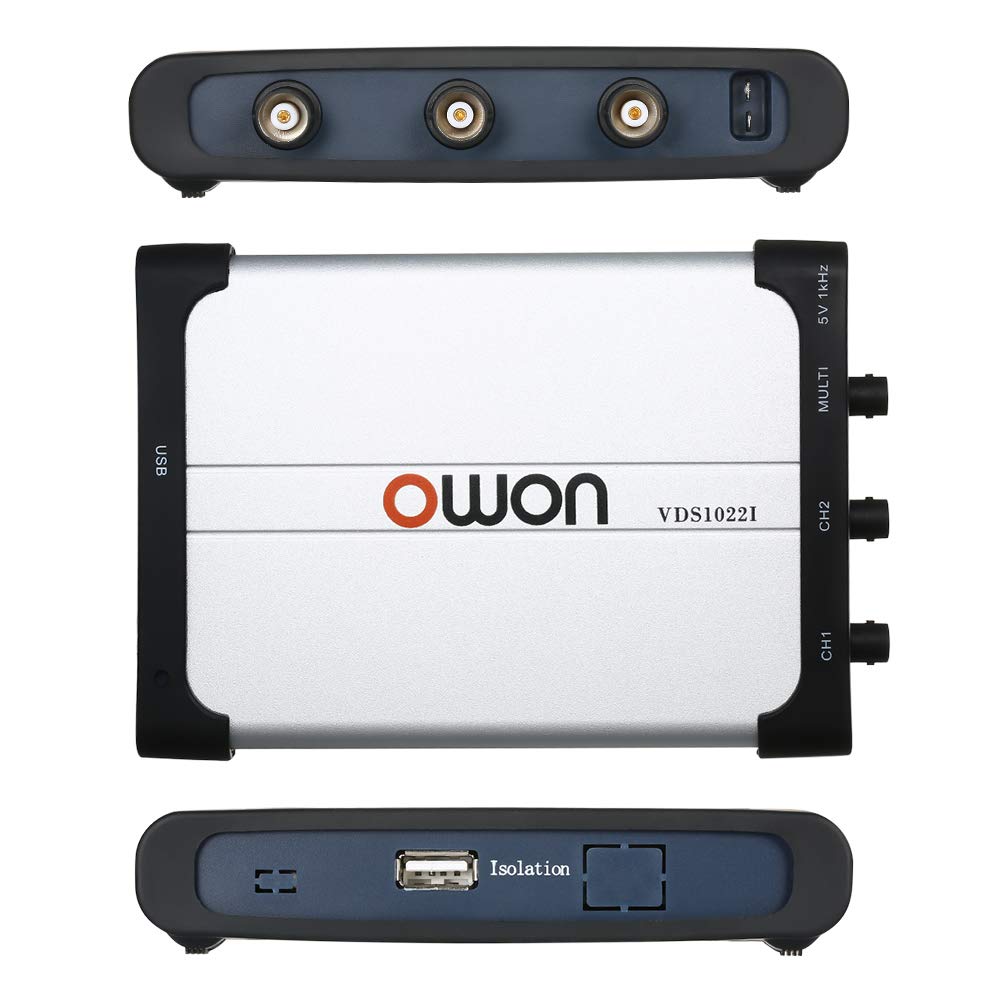
Image: Top and bottom views of the OWON VDS1022I. The bottom view shows the "Isolation" label, indicating the USB isolation feature.
The device features USB isolation, which helps to reduce noise and protect your computer from potential electrical surges from the measurement circuit.
3. Setup Guide
3.1 Software Installation
- Insert the provided software CD into your computer's CD-ROM drive.
- Locate and run the setup executable file. Follow the on-screen instructions to install the OWON oscilloscope software and necessary drivers.
- Alternatively, download the latest software and drivers from the official OWON website. Ensure you select the correct model (VDS1022I) and operating system.
- During installation, ensure that the oscilloscope is NOT connected to the PC until prompted, or until the software installation is complete. This helps ensure proper driver recognition.
3.2 Connecting the Oscilloscope
- Connect one end of the supplied USB cable to the USB port on the OWON VDS1022I unit.
- Connect the other end of the USB cable to an available USB port on your PC. The device is bus-powered, so no external power adapter is required.
- Your operating system should detect the device and, if drivers were installed correctly, recognize it as an OWON VDS1022I oscilloscope.
3.3 Probe Connection and Compensation
- Connect the oscilloscope probes to the CH1 and CH2 input BNC connectors on the device.
- Attach the probe ground clip to a known ground point in your circuit.
- To compensate the probe, connect the probe tip to the 5V 1KHz Probe Compensation output.
- Adjust the compensation screw on the probe body until a flat-top square wave is displayed on the software interface. This ensures accurate signal representation.
4. Operating Instructions
4.1 Launching the Software
After successful installation and connection, launch the OWON oscilloscope application from your desktop shortcut or Start Menu. The software interface will display the waveform acquisition window.
4.2 Basic Waveform Display
- Vertical Scale (Volts/Div): Adjust the vertical sensitivity for each channel using the controls in the software. This determines the voltage represented by each vertical division on the display.
- Horizontal Scale (Time/Div): Adjust the horizontal time base to control the time represented by each horizontal division. This affects the displayed duration of the waveform.
- Input Coupling: Select DC, AC, or GND coupling for each channel as needed.
- DC: Displays both AC and DC components of the signal.
- AC: Blocks the DC component, displaying only the AC component.
- GND: Disconnects the input signal, displaying a ground reference line.
4.3 Triggering
Triggering stabilizes repetitive waveforms and captures single-shot events. The VDS1022I supports various trigger modes:
- Edge Trigger: Triggers on a rising or falling edge of the input signal at a specified voltage level.
- Video Trigger: Triggers on standard video signals.
- Slope Trigger: Triggers on a signal's rise or fall time.
- Pulse Trigger: Triggers on pulses of specific width.
- Alternate Trigger: Allows triggering on two different channels alternately.
Adjust the trigger level and mode within the software to achieve a stable waveform display.
4.4 Measurements and Analysis
- Automatic Measurements: The software provides automatic measurements for parameters like Vpp, Vmax, Vmin, Freq, Period, RMS, etc. Select desired measurements from the menu.
- Cursors: Use voltage and time cursors to manually measure specific points on the waveform.
- FFT (Fast Fourier Transform): Access the FFT function to analyze the frequency components of your signal.
- X-Y Mode: Display the relationship between two signals in X-Y format, useful for phase comparisons or Lissajous figures.
5. Maintenance
- Cleaning: Use a soft, dry cloth to clean the exterior of the oscilloscope. For stubborn dirt, a slightly damp cloth with mild detergent can be used, ensuring no liquid enters the device.
- Storage: Store the device in a cool, dry place away from direct sunlight and extreme temperatures.
- Probe Care: Handle probes carefully. Avoid bending or stressing the cables excessively. Keep probe tips clean.
- Software Updates: Periodically check the OWON website for software and firmware updates to ensure optimal performance and access to new features.
6. Troubleshooting
6.1 Device Not Recognized by PC
- Ensure the USB cable is securely connected to both the oscilloscope and the PC.
- Verify that the correct drivers have been installed. Reinstall drivers if necessary, following the instructions in Section 3.1.
- Try connecting to a different USB port on your PC.
- Restart your computer and try again.
6.2 No Waveform Display or Unstable Waveform
- Check probe connections to the device and the circuit under test. Ensure ground clips are properly connected.
- Verify that the input coupling (DC/AC/GND) is set appropriately for your signal.
- Adjust the vertical (Volts/Div) and horizontal (Time/Div) scales to match the expected signal characteristics.
- Adjust the trigger level and trigger mode. An unstable waveform often indicates an incorrect trigger setting.
- Ensure the signal source is active and producing a signal within the oscilloscope's measurement range.
6.3 Software Issues or Crashes
- Ensure your operating system meets the minimum requirements for the OWON software.
- Update the software to the latest version from the OWON website.
- Close other demanding applications that might be consuming system resources.
- If issues persist, try reinstalling the software.
6.4 Limited Bandwidth or Signal Distortion
- The VDS1022I has a 25MHz bandwidth. Signals exceeding this frequency may be attenuated or distorted.
- Ensure probes are correctly compensated (refer to Section 3.3).
- For high-frequency measurements, ensure proper grounding and minimize cable lengths to reduce noise.
7. Specifications

Image: Dimensions of the OWON VDS1022I oscilloscope, showing approximate measurements of 180mm (7.09in) length, 125mm (4.92in) width, and 23mm (0.91in) thickness.
| Parameter | Value |
|---|---|
| Bandwidth | 25 MHz |
| Channels | 2 + 1 (external trigger) |
| Sample Rate | 100 MS/s (real-time) |
| Horizontal Scale (s/div) | 5 ns/div ~ 100 s/div (1-2-5 step) |
| Rise Time | ≤ 14 ns |
| Record Length | 5K points |
| Input Coupling | DC, AC, GND |
| Input Impedance | 1 MΩ ±2%, in parallel with 10 pF ±5 pF |
| Channels Isolation | 50Hz: 100:1, 10MHz: 40:1 |
| Max Input Voltage | 400V (PK - PK) (DC+AC, PK - PK) |
| DC Gain Accuracy | ±3% |
| Probe Attenuation Factor | 1X, 10X, 100X, 1000X |
| LF Respond (AC, -3dB) | ≥ 5Hz (at input, AC coupling, -3dB) |
| Sampling Rate / Relay Time Accuracy | 150 ps |
| Interpolation | sin(x) / x |
| Vertical Resolution (A/D) | 8 bits (2 channels simultaneously) |
| Vertical Sensitivity | 5 mV/div ~ 5 V/div |
| Communication Interface | USB 1.1 (isolation) |
| Product Dimensions | 6.69 x 4.72 x 0.71 inches (170 x 120 x 18 mm); 1.46 Pounds (0.66 kg) |
| Manufacturer | OWON |
8. Warranty and Support
OWON products are designed and manufactured to high-quality standards. For specific warranty information, please refer to the warranty card included with your product or visit the official OWON website. In case of technical issues, questions, or service requests, please contact OWON customer support through their official channels. Keep your purchase receipt as proof of purchase for warranty claims.


