1. Introduction
This manual provides detailed instructions for assembling and operating the Gikfun 6 Bits Digital LED Electronic Clock DIY Kit. This kit is designed for electronics enthusiasts and students to practice soldering skills and learn about digital clock circuitry. Upon successful assembly, the device functions as a precise digital clock with additional features.
2. Components List
Before beginning assembly, verify that all components listed below are present in your kit. Refer to the provided image for visual identification of parts.

Image 2.1: All components included in the Gikfun Digital LED Electronic Clock DIY Kit, laid out for inspection. This includes the PCB, LED modules, resistors, capacitors, transistors, ICs, buttons, buzzer, and power cable.

Image 2.2: Detailed table listing each component by name, specifications, and code for easy identification during assembly.
| SN | Name | Specifications | Code | SN | Name | Specifications | Code |
|---|---|---|---|---|---|---|---|
| 01 | Resistor | 1K | R9~R15 | 20 | Transistor | S8550 | Q1 |
| 02 | Resistor | 1K | R2~R8 | 21 | Transistor | S8550 | Q2 |
| 03 | Resistor | 2K | R16~R17 | 22 | Transistor | S8550 | Q3 |
| 04 | Resistor | 5.1K | R18 | 23 | Transistor | S8550 | Q4 |
| 05 | Resistor | 10K | R1 | 24 | Transistor | S8550 | Q5 |
| 06 | Ceramic Capacitor | 30P | C2 | 25 | Transistor | S8550 | Q6 |
| 07 | Ceramic Capacitor | 30P | C3 | 26 | Transistor | S8550 | Q7 |
| 08 | Electrolytic Capacitor | 104 | C4 | 27 | Chip | AT89C2051 | U1 |
| 09 | Electrolytic Capacitor | 104 | C5 | 28 | Chip | 78L05 | U2 |
| 10 | Electrolytic Capacitor | 10uF/25V | C1 | 29 | Crystal | 12MHz | Y1 |
| 11 | Electrolytic Capacitor | 100uF/16V | C6 | 30 | Socket | XH2.54 (Horizontal) 2P | J2 |
| 12 | LED | Φ 3 red | D1 | 31 | Socket | XH2.54 (Vertical) 2P | J1 |
| 13 | LED | Φ 3 red | D2 | 32 | Keys | 6*6*5 | S1 |
| 14 | LED | Φ 3 red | D3 | 33 | Keys | 6*6*5 | S2 |
| 15 | LED | Φ 3 red | D4 | 34 | Keys | 6*6*5 | S3 |
| 16 | Digital Tube | 0.4 inches 2-bit red | DS1 | 35 | IC Socket | 20P | U1 |
| 17 | Digital Tube | 0.4 inches 2-bit red | DS2 | 36 | PCB | 49*97.5mm | 1 |
| 18 | Digital Tube | 0.4 inches 2-bit red | DS3 | 37 | Power Wire | 2P (Single) L=150mm | 1 |
| 19 | Buzzer | 5V | U3 |
3. Assembly Instructions (Setup)
This section guides you through the assembly process. Basic soldering skills are required. Ensure you have a soldering iron, solder, desoldering wick/pump, and safety glasses.
3.1. Preparation
- Unpack all components and verify against the components list (Table 2.1).
- Familiarize yourself with the PCB layout and component markings.
- Prepare your soldering station: heat up the soldering iron, have solder ready, and ensure good ventilation.
3.2. Soldering Order Recommendation
It is generally recommended to solder components from shortest to tallest to facilitate easier assembly. Follow the markings on the PCB for correct component placement and orientation.
- Resistors (R1-R18): Solder all resistors first. Pay attention to their resistance values (indicated by color bands) and match them to the PCB markings (e.g., 1K, 2K, 5.1K, 10K).
- Diodes (D1-D4) and LEDs: Solder the four red LEDs (D1-D4) and any other diodes. Ensure correct polarity; the longer lead is typically the anode (+), and the shorter lead is the cathode (-), which usually aligns with a flat edge or marking on the PCB.
- Ceramic Capacitors (C2-C5): Solder the ceramic capacitors. These are non-polarized.
- Crystal (Y1): Solder the 12MHz crystal.
- Transistors (Q1-Q7): Solder the S8550 transistors. Ensure correct orientation as indicated by the flat side on the transistor matching the silkscreen on the PCB.
- Buttons (S1-S3): Solder the three push buttons.
- Electrolytic Capacitors (C1, C6): Solder the electrolytic capacitors (10uF/25V, 100uF/16V). These are polarized; the longer lead is positive (+), and the shorter lead (marked with a stripe on the capacitor body) is negative (-). Match the negative stripe to the corresponding marking on the PCB.
- Buzzer (U3): Solder the 5V buzzer. Observe polarity if indicated.
- IC Sockets (U1 for AT89C2051, U2 for 78L05): Solder the IC sockets. Ensure the notch on the socket aligns with the notch marking on the PCB silkscreen. This is crucial for correct IC orientation.
- Digital Tubes (DS1-DS3): Solder the 0.4-inch 2-bit red digital display modules.
- Power Sockets (J1, J2): Solder the XH2.54 sockets for power input.
3.3. Installing Integrated Circuits (ICs)
After all soldering is complete and the PCB has cooled, carefully insert the AT89C2051 and 78L05 ICs into their respective sockets (U1 and U2). Ensure the notch on the IC aligns with the notch on the socket and the PCB silkscreen. Gently press down until the IC is fully seated.
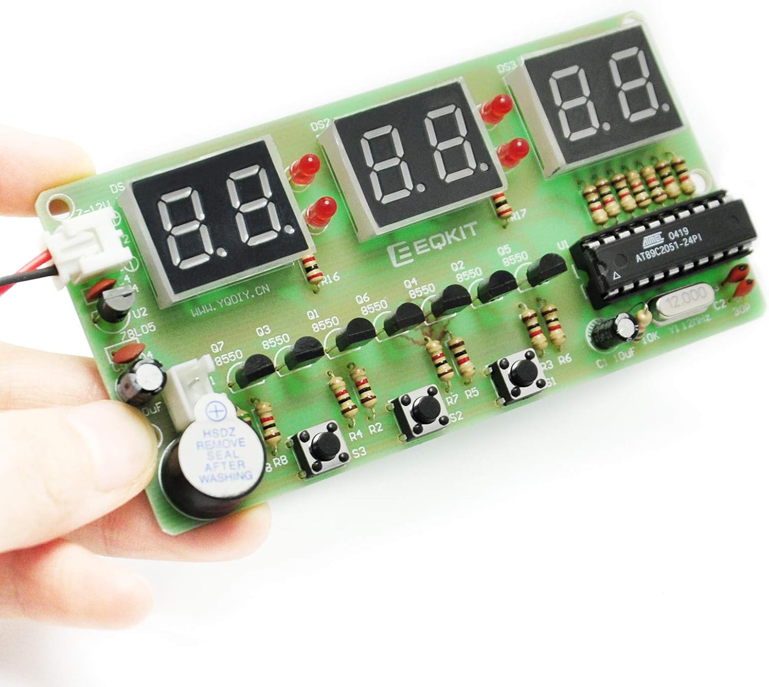
Image 3.1: An assembled Gikfun Digital LED Electronic Clock, demonstrating the placement of components on the PCB.

Image 3.2: The circuit diagram illustrating the connections and components of the digital clock.
4. Power Supply
The kit includes a 150mm single-head power supply line. The end with the terminal plugs directly into the PCB power supply socket (J1 or J2). The other end requires stripping and connection to a suitable power source.
- Input Voltage: The circuit is designed to operate with a 7-12V DC input. The 78L05 voltage regulator (U2) converts this to 5V for the microcontroller and other components.
- Recommended Power Source: While a 9V battery can be used, it is known to drain quickly (within 24 hours). For continuous operation, a regulated 7-12V DC power adapter (e.g., a USB power source with a suitable adapter cable) is highly recommended.
- Connection: Connect the positive (+) wire from your power source to the VCC pin of the power socket and the negative (-) wire to the GND pin.
5. Operating Instructions
The Gikfun Digital LED Electronic Clock features precise time display and several functions controlled by the three push buttons (S1, S2, S3).

Image 5.1: The assembled clock module, highlighting the three control buttons on the PCB.
5.1. Basic Functions
- Time Display: The clock displays time in a 24-hour format.
- Seconds Correction: Allows for fine-tuning of the time.
- Countdown Clock: Set a timer for a specific duration.
- Stopwatch: Measure elapsed time.
- Counter: A simple counting function.
- Hourly Chime: An audible alert at the top of each hour.
- Alarm Clock: Set a specific time for an alarm.
5.2. Button Operation (General Guide)
The exact button functions may vary slightly based on the firmware version. Typically, the buttons are used for:
- Mode Selection: Pressing one button (e.g., S1) cycles through different modes (Time, Alarm, Stopwatch, Countdown, etc.).
- Setting Adjustment: Once in a setting mode (e.g., setting time), other buttons (e.g., S2, S3) are used to increase/decrease values or move between digits.
- Confirmation/Start/Stop: A button might be used to confirm settings or to start/stop functions like the stopwatch or countdown.
Refer to the specific instructions provided with the kit's PDF manual for precise button functionalities and setting procedures.
6. Maintenance
- Cleaning: Keep the PCB and components free from dust and debris. Use a soft, dry brush or compressed air for cleaning. Avoid liquids.
- Power Supply: Ensure a stable power supply within the recommended voltage range (7-12V DC). Unstable power can affect performance and component lifespan.
- Storage: Store the assembled clock in a dry environment, away from extreme temperatures and direct sunlight.
7. Troubleshooting
- Clock does not power on or displays random characters:
- Check power connections and ensure the power supply is providing the correct voltage (7-12V DC).
- Verify the polarity of electrolytic capacitors and LEDs. Incorrect polarity can prevent operation or damage components.
- Inspect all solder joints for cold joints, bridges, or unsoldered pins. Re-solder as necessary.
- Ensure the AT89C2051 and 78L05 ICs are correctly seated in their sockets and oriented correctly (notch alignment).
- Check for any defective components. Some users have reported faulty LEDs or voltage regulators (78L05). A multimeter can help test components.
- Digital displays are not lighting up correctly or segments are missing:
- Check solder joints for the digital display modules and their associated resistors.
- Ensure the LEDs (D1-D4) are correctly oriented and soldered.
- Verify that the transistors (Q1-Q7) are correctly oriented and soldered, as they drive the display segments.
- Clock loses time or is inaccurate:
- Ensure the 12MHz crystal (Y1) is correctly soldered and not damaged.
- Check the ceramic capacitors (C2, C3) associated with the crystal.
- Buzzer does not sound:
- Check the buzzer's polarity and solder connections.
- Verify the associated transistor (Q7) and resistor (R18) are correctly installed.
- High power consumption (e.g., 9V battery drains quickly):
- This is a known characteristic of the design when using 9V batteries. Consider using a regulated DC power adapter (7-12V) for sustained operation.
8. Specifications
- Model: AT89C2051 EK1323
- Microcontroller: AT89C2051
- Display: 6-digit LED (0.4 inches, 2-bit red digital tubes x3)
- Power Input: 7-12V DC
- Functions: Time display (24-hour format), seconds correction, countdown clock, stopwatch, counter, hourly chime, alarm clock.
- PCB Dimensions: 49 x 97.5 mm
- Material: FR-4 PCB, Iron (components)
- Item Weight: Approximately 1.41 ounces (40 grams)
9. Support Information
For further assistance or inquiries regarding the Gikfun 6 Bits Digital LED Electronic Clock DIY Kit, please refer to the official Gikfun support channels or the online PDF manual mentioned in the product description. You can also visit the Gikfun Store on Amazon for additional resources.


