1. Introduction
This manual provides essential information for the safe and efficient operation of your EASUN POWER PWM Solar Charge Controller. This device is designed to manage the power flow from your solar panels to your battery bank, ensuring optimal charging and protecting your batteries from overcharge and over-discharge. It is compatible with 12V/24V lead-acid battery systems (OPEN, AGM, GEL types) and features an adjustable LCD display and dual USB ports for convenience.

Figure 1: Front view of the EASUN POWER 30A PWM Solar Charge Controller, showing the LCD display, control buttons, and USB ports.
2. Key Features
- Automatic Voltage Recognition: Automatically detects 12V or 24V battery systems.
- PWM Charge Management: Fully 4-stage PWM charge management for efficient battery charging.
- LCD Display: Large LCD display showing all adjustable parameters and system status.
- Dual USB Ports: 5V/2.5A (max) USB output for charging mobile devices.
- Comprehensive Protections: Built-in short-circuit protection, open-circuit protection, reverse protection, over-load protection, dual MOSFET reverse current protection, and low heat production.
- Battery Compatibility: Specifically designed for lead-acid batteries (OPEN, AGM, GEL).

Figure 2: Overview of the intelligent protection features including over-discharging, overcharging, overload, short circuit, reverse polarity, reverse current, and temperature compensation.
3. Safety Precautions
Please read all instructions carefully before installation and operation. Failure to follow these instructions may result in damage to the unit, personal injury, or property damage.
- Ensure the battery voltage is sufficient for the controller to recognize the battery type before first installation.
- The charge controller is only suitable for lead-acid batteries (OPEN, AGM, GEL). Do not connect other types of batteries (e.g., nickel hydride, lithium-ion).
- Install the controller indoors, away from direct sunlight, high temperatures, and humid environments.
- The controller will heat up during operation; ensure good ventilation.
- The battery cable should be as short as possible to minimize loss.
- Always connect the battery to the controller first, then the solar panel, and finally the load. Disconnect in the reverse order.
- Ensure all connections are tight and secure to avoid loose connections that can cause excessive heat.
- Do not attempt to disassemble or repair the controller yourself. Contact qualified personnel for service.
4. Setup and Installation
Follow these steps for proper installation of your solar charge controller:
- Prepare Cables: Ensure you have appropriate gauge cables for your solar panel, battery, and load connections.
- Connect Battery: Connect the battery to the charge controller first. Ensure correct polarity (+ to + and - to -). The controller will automatically detect 12V or 24V.
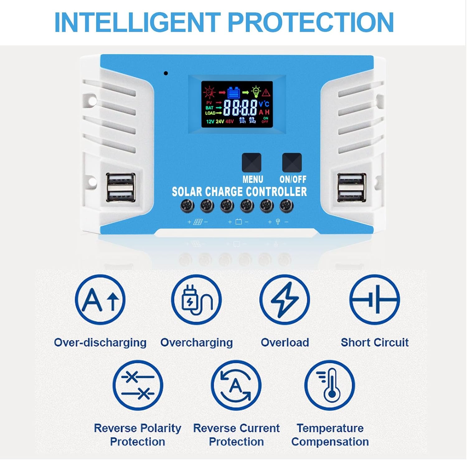
Figure 3: The controller is compatible with various lead-acid battery types including AGM, GEL, and FLD. Lithium batteries are not supported by this model.
- Connect Solar Panel: Connect the solar panel to the charge controller. Again, observe correct polarity. The maximum solar input voltage is 25V for a 12V battery system and 50V for a 24V battery system.
- Connect Load: Connect your DC load to the charge controller. Ensure the load current does not exceed the controller's rated current.
Figure 4: Connection diagram showing the sequence: Battery first, then PV panel, then DC load. Disconnect in reverse order.
Important Note: Always connect the battery first, then the solar panel, and then the load. When disconnecting, disconnect the solar panel first, then the battery.
5. Operating Instructions
5.1 LCD Display and Buttons
The controller features a large LCD display for monitoring system status and two buttons for navigation and settings.

Figure 5: The LCD screen displays real-time data, and the dual USB ports provide 5V output for charging devices.
- MENU Button: Used to cycle through display screens and enter/exit parameter setting mode.
- ON/OFF Button: Used to turn the load output on or off. In parameter setting mode, it's used to adjust values.
5.2 Charging Stages (PWM)
The controller employs a 4-stage PWM charging algorithm to optimize battery life and performance:
- Bulk Charge: Charges the battery at maximum current until voltage rises to the absorption level.
- Absorption Charge: Charges at constant voltage to ensure the battery is fully charged.
- Float Charge: Maintains the battery at a constant voltage, compensating for self-discharge and keeping the battery topped off.
- Equalization Charge (Optional): Periodically overcharges the battery to balance cell voltages and prevent sulfation (for certain battery types).

Figure 6: Visual representation of the PWM three-stage charging process.
6. Maintenance
Regular maintenance ensures the longevity and optimal performance of your solar charge controller:
- Check Connections: Periodically inspect all wiring connections to the controller, battery, solar panel, and load. Ensure they are tight, secure, and free from corrosion.
- Clean Controller: Keep the controller clean and free from dust and debris. Use a dry cloth to wipe the surface. Do not use liquid cleaners.
- Ventilation: Ensure the area around the controller is well-ventilated to prevent overheating.
- Battery Inspection: Regularly check the battery terminals for corrosion and clean them if necessary. Ensure the battery is in good condition.
7. Troubleshooting
This section provides solutions to common issues you might encounter.
| Problem | Possible Cause | Solution |
|---|---|---|
| Controller not turning on / No display | Battery not connected or reverse polarity; Battery voltage too low. | Check battery connections and polarity. Ensure battery voltage is above minimum operating voltage. |
| Battery not charging | Solar panel not connected or reverse polarity; Insufficient sunlight; Damaged solar panel or cable. | Check solar panel connections and polarity. Ensure panels are in direct sunlight. Inspect panels and cables for damage. |
| Load not working | Load output turned off; Overload protection activated; Short circuit in load. | Press the ON/OFF button to activate load. Reduce load. Check load wiring for short circuits. |
| Overcharge/Over-discharge warning | Incorrect battery type setting; Battery nearing end of life. | Ensure correct battery type is selected (if adjustable). Consider replacing old battery. |
8. Specifications
| Parameter | Value |
|---|---|
| Model | 30A |
| System Voltage | 12V/24V Auto |
| Max Solar Input Voltage (12V battery) | 25V |
| Max Solar Input Voltage (24V battery) | 50V |
| Max Solar Panel Power (12V battery) | 360W |
| Max Solar Panel Power (24V battery) | 720W |
| USB Output | 5V/2.5A (max) |
| Display Type | LCD |
| Material | Metal |
| Dimensions | 20.7 x 10.79 x 4.9 cm |
| Weight | 422 g |
| Manufacturer | EASUN POWER |
| UPC | 742500941734 |
Figure 7: The controller's dimensions (161mm x 91mm) and examples of suitable applications such as RVs, residential solar, marine, and off-grid setups.
9. Warranty and Support
EASUN POWER provides a 12-month warranty for this product, covering failures under normal usage. Accidental damage due to environmental causes or incorrect usage and installation is not covered but may be serviceable.
We also offer lifetime technical support. For any warranty issues, technical assistance, or questions, please contact the seller directly.
The product is CE certified and undergoes 100% QC before shipment, ensuring high quality and reliability.


