1. Introduction
This manual provides detailed instructions for the safe and effective use of your Proster Digital Clamp Meter TRMS 2000counts. This versatile instrument is designed for measuring AC current, AC/DC voltage, resistance, continuity, temperature, diode, and frequency. It features auto-ranging, True RMS measurement, and Non-Contact Voltage (NCV) detection, making it an essential tool for household, laboratory, factory, and radio-technology applications.
2. Safety Information
Please read all safety warnings and operating instructions carefully before using this meter. Failure to do so may result in electric shock, fire, or damage to the meter.
- Always adhere to local and national safety codes.
- Do not use the meter if it appears damaged or if the insulation on the test leads is compromised.
- Ensure the rotary switch is in the correct position for the desired measurement before connecting the test leads.
- Do not exceed the maximum input values for any function. This meter is rated for CAT II 600V and CAT III 300V.
- Be cautious when working with voltages above 30V AC RMS, 42V peak, or 60V DC, as they pose a shock hazard.
- The clamp jaw is designed to measure AC current only. Do not attempt to measure DC current with the clamp.
- When measuring current with the clamp, ensure only a single conductor passes through the clamp jaw. Measuring two conductors (e.g., live and neutral) will result in a zero reading.
- Remove test leads from the circuit before changing functions.
3. Package Contents
Verify that all items are present and undamaged upon opening the package:
- Proster Digital Clamp Meter (CM2000C)
- Test Leads (Red and Black)
- Temperature Probe
- 2 x LR44 Batteries (pre-installed or included separately)
- Soft Zippered Pouch
- Mini Screwdriver (for battery compartment)
- User Manual

Figure 3.1: Included accessories and the Proster Digital Clamp Meter.
4. Product Overview
Familiarize yourself with the main components of your clamp meter:
- Clamp Jaw: Used for non-contact AC current measurement. Maximum opening size is 28mm.
- Function Rotary Switch: Selects the desired measurement function (e.g., AC Current, AC/DC Voltage, Resistance, NCV, Temperature).
- LCD Display: Shows measurement readings, units, and function indicators. Features a backlight for low-light conditions.
- Input Jacks: Connect test leads for voltage, resistance, continuity, diode, and temperature measurements.
- Buttons: Include SELECT (for switching between AC/DC or other sub-functions), MAX/MIN (for recording maximum/minimum values), RANGE (for manual ranging), HOLD (for freezing the display reading), and Backlight/Flashlight activation.

Figure 4.1: Key components of the Clamp Meter.
5. Setup
5.1 Battery Installation
The meter requires 2 x LR44 batteries. If the low battery indicator appears on the display, or if the meter does not power on, replace the batteries:
- Ensure the meter is turned OFF.
- Locate the battery compartment on the back of the meter.
- Use the included mini screwdriver to loosen the screw and open the battery cover.
- Insert the 2 x LR44 batteries, observing the correct polarity (+/-).
- Replace the battery cover and tighten the screw.
5.2 Connecting Test Leads
For most measurements (voltage, resistance, continuity, diode, temperature), the test leads must be connected:
- Insert the red test lead into the VΩHz input jack.
- Insert the black test lead into the COM (common) input jack.
6. Operating Instructions
6.1 AC Current Measurement (Clamp)
This meter can measure AC current up to 600A without breaking the circuit.
- Turn the rotary switch to the '200A/600A' or '2A/20A' AC current range. The meter will auto-range within the selected setting.
- Open the clamp jaw by pressing the trigger.
- Enclose only one conductor (e.g., the live wire) of the circuit within the clamp jaw. Ensure the jaw is fully closed.
- Read the AC current value on the LCD display.

Figure 6.1: Measuring AC current with the clamp jaw.
6.2 AC/DC Voltage Measurement
The meter can measure AC and DC voltages up to 600V.
- Connect the red test lead to the VΩHz jack and the black test lead to the COM jack.
- Turn the rotary switch to the 'V~' for AC Voltage or 'V=' for DC Voltage. The meter will auto-range.
- Touch the red test probe to the positive side of the circuit and the black test probe to the negative side (or ground).
- Read the voltage value on the LCD display.
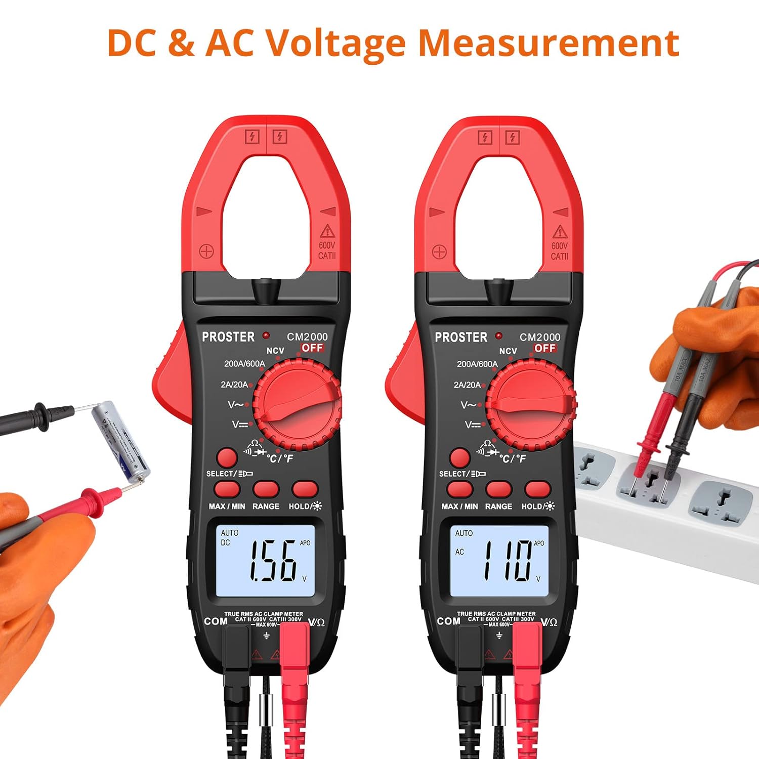
Figure 6.2: AC and DC Voltage Measurement.
6.3 Resistance Measurement
Measure resistance up to 20MΩ.
- Connect the test leads as described in Section 5.2.
- Turn the rotary switch to the 'Ω' position.
- Ensure the circuit or component is de-energized before measuring resistance.
- Touch the test probes across the component or circuit to be measured.
- Read the resistance value on the LCD display.
6.4 Continuity Test
Test for continuity in a circuit or wire.
- Connect the test leads as described in Section 5.2.
- Turn the rotary switch to the 'Ω' position and press the SELECT button until the continuity symbol (speaker icon) appears.
- Ensure the circuit or component is de-energized.
- Touch the test probes across the circuit or component.
- If continuity exists (resistance less than approximately 50Ω), the meter will emit an audible beep.
6.5 Diode Test
Test the forward voltage drop of a diode.
- Connect the test leads as described in Section 5.2.
- Turn the rotary switch to the 'Ω' position and press the SELECT button until the diode symbol appears.
- Touch the red test probe to the anode and the black test probe to the cathode of the diode.
- Read the forward voltage drop on the LCD display. For a good silicon diode, this is typically around 0.5V to 0.8V. An open circuit (OL) indicates a faulty diode or incorrect polarity.
6.6 Temperature Measurement
Measure temperature using the included temperature probe.
- Connect the temperature probe to the VΩHz and COM input jacks, observing polarity if indicated on the probe.
- Turn the rotary switch to the '°C/°F' position.
- Press the SELECT button to switch between Celsius (°C) and Fahrenheit (°F).
- Place the tip of the temperature probe on or in the object/environment to be measured.
- Read the temperature value on the LCD display.

Figure 6.3: Measuring temperature with the probe.
6.7 NCV (Non-Contact Voltage) Detection
Detect the presence of AC voltage without direct contact.
- Turn the rotary switch to the 'NCV' position.
- Move the top end of the meter (where the clamp jaw is) close to the conductor or outlet you suspect has AC voltage.
- The meter will emit an audible beep and the NCV indicator light will flash if AC voltage is detected (typically 90V-1000V). The intensity of the beeping and flashing increases with stronger voltage.

Figure 6.4: Non-Contact Voltage detection in progress.
6.8 Frequency (Hz) Measurement
Measure the frequency of an AC signal.
- Connect the test leads as described in Section 5.2.
- Turn the rotary switch to an AC Voltage ('V~') range.
- Press the SELECT button repeatedly until 'Hz' appears on the display.
- Connect the test probes across the AC voltage source.
- Read the frequency value on the LCD display.
6.9 Special Functions
- True RMS: This meter provides True RMS measurements for AC voltage and current, ensuring accurate readings for non-sinusoidal waveforms.
- Auto-Ranging: The meter automatically selects the appropriate measurement range, simplifying operation. You can press the 'RANGE' button to switch to manual ranging if desired.
- Data Hold: Press the 'HOLD' button to freeze the current reading on the display. Press again to release.
- Backlight/Flashlight: Press and hold the backlight button to turn on the display backlight. A short press of the same button activates the built-in flashlight for illuminating dark work areas.
- Auto Power Off (APO): To conserve battery life, the meter will automatically power off after approximately 15 minutes of inactivity. Press any button or turn the rotary switch to reactivate.
- MAX/MIN Measurement: Press the 'MAX/MIN' button to enter MAX/MIN recording mode. The meter will display the maximum or minimum value recorded since entering this mode. Press again to cycle between MAX, MIN, and current reading.
7. Maintenance
7.1 Cleaning
Wipe the case with a damp cloth and mild detergent. Do not use abrasives or solvents. Keep the input terminals free of dirt and moisture.
7.2 Battery Replacement
Refer to Section 5.1 for instructions on replacing the batteries when the low battery indicator appears.
7.3 Storage
If the meter is not to be used for an extended period, remove the batteries to prevent leakage and store the meter in its soft zippered pouch in a cool, dry place.
8. Troubleshooting
- Display shows "OL": This indicates an overload (measurement exceeds the meter's range) or an open circuit (for resistance/continuity). Check your connections and ensure the measured value is within the meter's capabilities.
- No reading when measuring AC current with clamp: Ensure only a single wire is enclosed within the clamp jaw. If two wires (e.g., live and neutral) are clamped, the magnetic fields will cancel out, resulting in a zero reading.
- Meter does not power on or display is dim: Check battery installation and replace batteries if necessary (refer to Section 5.1).
- Inaccurate readings: Ensure test leads are fully inserted, the correct function is selected, and the meter is used within its specified operating conditions.
- Cannot measure DC current with clamp: This model's clamp jaw is designed for AC current only. For DC current measurement, a different type of clamp meter (e.g., Hall effect sensor based) is required. Please refer to other Proster clamp meter models for DC current capabilities.
9. Specifications
| Feature | Specification |
|---|---|
| Model Number | CM2000C |
| Measurement Type | Digital Clamp Meter |
| Display Counts | 2000 Counts |
| AC Current Range | 2A/20A/200A/600A |
| AC/DC Voltage Range | Up to 600V |
| Resistance Range | 200Ω - 20MΩ |
| Temperature Measurement | Yes (with probe) |
| Frequency (Hz) | Yes |
| Continuity Test | Yes (with audible beep) |
| Diode Test | Yes |
| NCV (Non-Contact Voltage) | Yes (90V-1000V AC) |
| True RMS | Yes |
| Auto-Ranging | Yes |
| Data Hold | Yes |
| Backlight | Yes |
| Flashlight | Yes |
| Auto Power Off | Approx. 15 minutes |
| Power Source | 2 x LR44 Batteries (included) |
| Item Weight | 0.2 Kilograms |
| Dimensions | 21.4 x 11.4 x 4.9 cm (Parcel Dimensions) |
| Manufacturer | Proster Trading Limited |

Figure 9.1: Physical dimensions of the Clamp Meter.
10. Warranty and Support
PROSTER products are designed for reliability and performance. For any questions regarding the operation, maintenance, or troubleshooting of your Proster Digital Clamp Meter, please refer to the contact information provided with your purchase or visit the official PROSTER website for support resources.


