1. Introduction
Thank you for choosing the Walfront BLDC Motor Controller. This high-efficiency, compact, and lightweight brushless DC motor driver board is designed for various applications requiring precise motor control, such as drones and RC cars. This manual provides essential information for the safe and effective use of your motor controller. Please read it thoroughly before installation and operation.
2. Safety Information
- Always disconnect power before making any connections or disconnections to prevent electric shock or damage to the device.
- Ensure correct polarity when connecting power. Incorrect polarity can cause irreversible damage to the controller.
- Do not exceed the specified voltage (DC 12V-36V) or current (15A) limits.
- Operate the controller within the recommended temperature range (-40 to 85°C) and humidity (90% RH).
- Avoid short circuits on any terminals.
- Keep the controller away from moisture, dust, and corrosive substances.
- Professional installation is recommended for users unfamiliar with electronic wiring.
3. Product Overview
3.1 Key Features
- High Quality Construction: Made from durable materials for extended service life and reliable performance.
- Efficient Performance: Features low power consumption, high reliability, and high efficiency for optimal motor operation.
- Compact Design: Small form factor makes it easy to integrate, carry, and store, enhancing operational efficiency.
- Multi-functional Protection: Includes undervoltage protection to prevent damage from instantaneous high currents, overcurrent protection, and short-circuit protection for safe motor driving.
- Wide Voltage Compatibility: Supports DC 12V-36V power input, making it suitable for a broad range of applications with brushless DC motors.
3.2 Components
The Walfront BLDC Motor Controller board includes power input terminals, motor output terminals (U, V, W), Hall sensor input terminals (Ha, Hb, Hc), and control signal input terminals (Enable, Speed, Direction).

Figure 1: Top and bottom view of the Walfront BLDC Motor Controller board. This image shows the layout of components on both sides of the circuit board, including the MOSFETs on the bottom and capacitors and control ICs on the top.

Figure 2: Close-up view of the capacitors on the Walfront BLDC Motor Controller. These capacitors are rated 220uF 50V, providing power filtering for stable operation.
4. Specifications
| Parameter | Value |
|---|---|
| Operating Voltage | DC 12V - 36V |
| Operating Current | <= 15A |
| Driver Power | <= 500W |
| Speed Voltage | 0.1V - 5V |
| Operating Temperature | -40°C to 85°C |
| Humidity | 90% RH |
| Product Dimensions | 10 x 4 x 10 cm (approx.) |
| Product Weight | 30 g |
| Protection Features | Stall prevention, Overcurrent protection, Short-circuit protection |
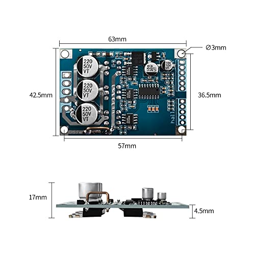
Figure 3: Physical dimensions of the Walfront BLDC Motor Controller board. The board measures approximately 63mm x 42.5mm with a height of 17mm.

Figure 4: Visual summary of key specifications for the 12-36V 500W brushless motor controller, including operating voltage, current, power, speed voltage, temperature, humidity, and protection features.
5. Setup and Wiring
Proper wiring is crucial for the correct and safe operation of the BLDC motor controller. Refer to the wiring diagram below and follow the instructions carefully.
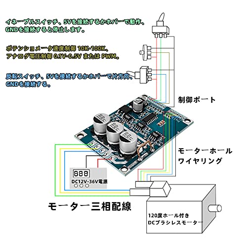
Figure 5: Detailed wiring diagram for the Walfront BLDC Motor Controller. This diagram illustrates connections for power (DC 12V-36V), motor three-phase wiring, Hall sensor wiring, and control signals (enable, speed potentiometer, reverse switch).
5.1 Power Connection
- Connect your DC 12V-36V power supply to the designated power input terminals on the board. Ensure correct polarity (+ and -).
5.2 Motor Wiring
- Connect the three-phase wires of your brushless DC motor to the U, V, W output terminals on the controller board.
- If your motor has Hall sensors, connect the Hall sensor wires (Ha, Hb, Hc) and their corresponding 5V and GND wires to the Hall sensor input terminals on the controller.
5.3 Control Port Connections
- Enable Switch: Connect an enable switch. Connecting 5V to this pin enables operation, and connecting to GND stops operation.
- Speed Control: Use a 10K-100K potentiometer for speed control. Alternatively, an analog voltage input (0.1V-5V) or PWM signal can be used.
- Reverse Switch: Connect a reverse switch. Connecting 5V to this pin sets one direction, and connecting to GND sets the opposite direction.
6. Operating Instructions
Once all connections are securely made and verified, you can proceed with operating the motor controller.
- Power On: Apply power to the controller within the specified voltage range (DC 12V-36V).
- Enable Motor: Ensure the enable switch is set to the 'ON' position (connected to 5V) to allow motor operation.
- Adjust Speed: Use the connected potentiometer or provide the appropriate analog voltage/PWM signal to the speed control input to adjust the motor's rotational speed. The motor will accelerate to the set speed over approximately 3 seconds due to the soft-start feature.
- Change Direction: Toggle the reverse switch to change the motor's direction of rotation.
- Power Off: Disconnect the power supply to turn off the motor and controller.
7. Maintenance
To ensure the longevity and optimal performance of your Walfront BLDC Motor Controller, follow these maintenance guidelines:
- Keep Clean: Regularly clean the board to remove dust and debris, which can affect heat dissipation and component performance. Use a soft, dry brush or compressed air.
- Inspect Connections: Periodically check all wiring connections to ensure they are secure and free from corrosion. Loose connections can lead to intermittent operation or damage.
- Environmental Control: Operate and store the controller in a dry, well-ventilated environment within the specified temperature and humidity ranges.
- Avoid Physical Stress: Do not bend or apply excessive force to the board or its components. Ensure proper mounting to prevent vibration-induced damage.
8. Troubleshooting
If you encounter issues with your Walfront BLDC Motor Controller, refer to the following troubleshooting steps:
- Motor Not Spinning:
- Verify that the power supply is connected correctly and providing the specified voltage (12V-36V DC).
- Check all motor phase wire connections (U, V, W) and Hall sensor connections (Ha, Hb, Hc, 5V, GND) for proper seating and continuity.
- Ensure the enable switch is in the 'ON' position (connected to 5V).
- Confirm that the speed control input is receiving a valid signal (0.1V-5V analog or PWM).
- If using a Hall sensor motor, ensure the Hall sensors are functioning correctly. Some motors may vibrate instead of spinning if Hall sensor signals are incorrect or missing.
- Controller Overheating:
- Ensure the motor current does not exceed 15A. Overloading the motor can cause excessive heat.
- Verify that the motor is not stalled or experiencing excessive mechanical resistance.
- Check for any short circuits in the motor wiring or on the board itself.
- Ensure adequate ventilation around the controller. If possible, consider adding a heatsink if operating at high loads or ambient temperatures. Note: Some units may have uneven soldering on FETs, making heatsink attachment difficult.
- Erratic Motor Behavior:
- Inspect all signal wires for interference or loose connections.
- Ensure the control signals (speed, direction) are stable and within the specified ranges.
- Verify that the motor's Hall sensors are correctly aligned and providing accurate feedback.
If the problem persists after following these steps, please contact Walfront customer support for further assistance.
9. Warranty and Support
Walfront products are designed for reliability and performance. While specific warranty details may vary by region and retailer, Walfront typically offers support for manufacturing defects. For warranty claims, technical assistance, or any product-related inquiries, please refer to your purchase documentation or contact Walfront customer service through the retailer where the product was purchased.
Please have your model number (Wal frontg9nmdcgx78) and purchase date available when contacting support.