
Introduction
This manual provides essential instructions for the installation, operation, and maintenance of the FidgetGear HP Odense Intgel H110 Envy Pavilion Motherboard (Model: 799929-001 IPM17-DD). Please read this manual thoroughly before proceeding with installation to ensure proper functionality and to prevent damage to the component or other system parts.

Figure 1: Overview of the FidgetGear HP Odense Intgel H110 Envy Pavilion Motherboard. This image displays the full layout of the motherboard, including the CPU socket, RAM slots, PCIe slots, and various connectors.
1. Setup and Installation
Before beginning installation, ensure your system is powered off and disconnected from the main power supply. Wear an anti-static wrist strap to prevent electrostatic discharge (ESD) damage to components.
1.1 Component Compatibility
- CPU Socket: LGA 1151
- Compatible Processors: Intel 6th Gen and later (e.g., i5-6600K, i7-7700K, i9-9900K)
- Chipset Type: Intel H110
- RAM Memory Technology: DDR4
- Memory Storage Capacity: Up to 16 GB (specific configuration may vary)
1.2 Motherboard Installation
- Prepare the Case: Ensure the computer case is ready for motherboard installation. Install the I/O shield provided with your case or system.
- Mount the Motherboard: Carefully align the motherboard with the standoffs in your computer case. Secure the motherboard using appropriate screws. Do not overtighten.
- Install CPU: Open the CPU socket lever, align the CPU with the socket (matching the golden triangle on the CPU to the triangle on the socket), gently place the CPU into the socket, and close the lever to secure it.
- Install CPU Cooler: Attach the CPU cooler according to its manufacturer's instructions. Ensure proper thermal paste application.
- Install RAM: Open the clips on the DDR4 memory slots. Align the RAM modules with the slots, ensuring the notch on the module matches the notch in the slot. Press down firmly on both ends until the clips snap into place.
- Connect Power Supply: Connect the 24-pin ATX power connector and the 4-pin or 8-pin CPU power connector from your power supply to the corresponding ports on the motherboard.
- Connect Storage Devices: Connect SATA data cables from your storage drives (HDD/SSD) to the SATA ports on the motherboard. Connect the corresponding power cables from the power supply to the drives.
- Connect Front Panel Connectors: Connect the power button, reset button, HDD LED, power LED, and USB/audio headers from your case's front panel to the appropriate pins on the motherboard. Refer to your case manual for specific pin layouts.
- Connect Peripherals: Connect external peripherals such as keyboard, mouse, and monitor to the rear I/O ports.
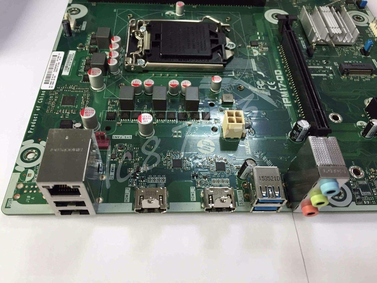
Figure 2: Close-up view of the motherboard's rear I/O ports. This image highlights the various connectivity options available, including USB ports, HDMI, and audio jacks, essential for connecting external devices.
2. Operating Instructions
Once all components are installed and connected, you can proceed with initial system boot-up.
2.1 Initial Boot and BIOS Access
- Power On: Connect the power cord to your power supply and press the power button on your computer case.
- BIOS/UEFI Access: During the initial boot sequence, repeatedly press the designated key (commonly DEL, F2, F10, or F12) to enter the BIOS/UEFI setup utility. Consult your system's documentation for the exact key.
- Configure Settings: Within the BIOS/UEFI, you can configure boot order, system time, and other hardware settings. Save changes and exit to continue booting.
2.2 Operating System Installation
Install your preferred operating system (e.g., Windows XP, as listed in specifications, or a more modern OS compatible with H110 chipset) from a bootable USB drive or optical media. Follow the on-screen instructions for installation.
2.3 Driver Installation
After operating system installation, install the necessary drivers for the motherboard's chipset, audio, network, and other integrated components. These drivers are typically available on the manufacturer's website or included with your system's recovery media.
3. Maintenance
Regular maintenance helps ensure the longevity and stable operation of your motherboard and system.
3.1 Cleaning
- Periodically clean dust from the motherboard and components using compressed air. Ensure the system is powered off and unplugged before cleaning.
- Avoid using liquid cleaners directly on the motherboard.
3.2 BIOS/UEFI Updates
Check the manufacturer's website for BIOS/UEFI updates. Updates can improve stability, add support for new hardware, or fix bugs. Follow the update instructions carefully to avoid system damage.
4. Troubleshooting
This section addresses common issues you might encounter.
4.1 No Power / No Boot
- Check Power Connections: Ensure all power cables (24-pin ATX, CPU power) are securely connected to the motherboard and power supply.
- Test Power Supply: If possible, test the power supply with another system or a power supply tester.
- Verify Front Panel Connections: Ensure the power button connector is correctly attached to the motherboard.
4.2 No Display Output
- Check Monitor Connection: Ensure the monitor cable is securely connected to the motherboard's video output (if using integrated graphics) or the discrete graphics card.
- Reseat Components: Power off and unplug the system. Reseat the RAM modules and any installed graphics cards.
- Clear CMOS: Refer to your motherboard's documentation for instructions on how to clear the CMOS (Complementary Metal-Oxide-Semiconductor) settings, which can resolve boot issues.
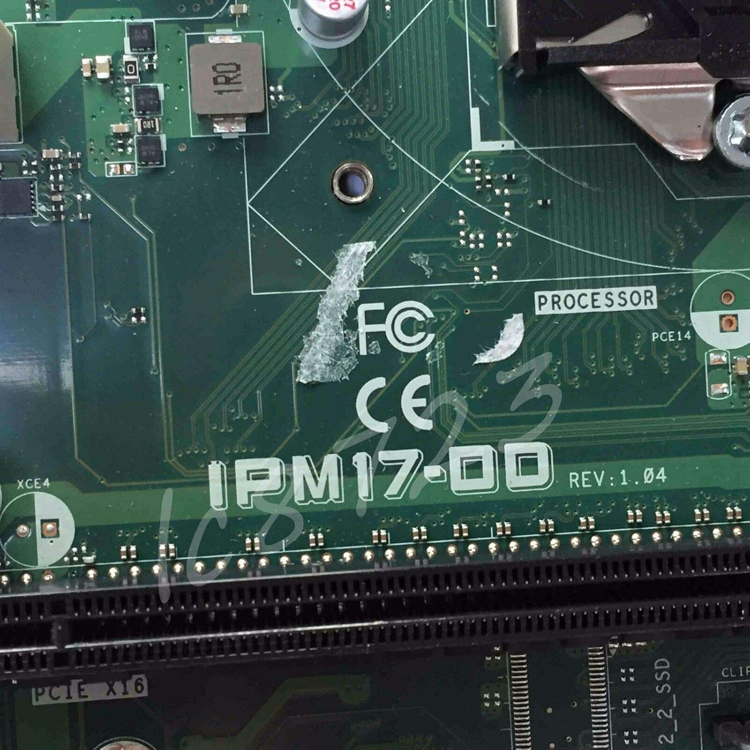
Figure 3: Close-up of the IPM17-DD model designation and processor area on the motherboard. This view helps in identifying the specific model and verifying component placement.
5. Specifications
Key technical specifications for the FidgetGear HP Odense Intgel H110 Envy Pavilion Motherboard (Model: 799929-001 IPM17-DD).
| Feature | Detail |
|---|---|
| Brand | FidgetGear |
| Model Name | IPM17-DD |
| Item Model Number | 799929-001 |
| CPU Socket | LGA 1151 |
| Compatible Processors | Intel 6th Gen and later (e.g., i5-6600K, i7-7700K, i9-9900K) |
| Chipset Type | Intel H110 |
| RAM Memory Technology | DDR4 |
| Memory Clock Speed | 3.5 GHz (Note: This typically refers to a CPU base clock, not RAM speed.) |
| Memory Storage Capacity | 16 GB (Maximum supported RAM capacity) |
| Compatible Devices | Personal Computer |
| Platform | Windows XP (Note: Modern operating systems are generally recommended for optimal performance and security.) |

Figure 4: Detailed view of the product label on the motherboard, showing part numbers and manufacturing information. This label includes SP# 799929-001, AS# 799929-001, PEURU0B0Z9NFXX, and 144758500003158, confirming the model identification and other manufacturing details.
6. Warranty Information
This product is typically covered by a limited warranty provided by the seller or manufacturer. Please refer to your purchase documentation or contact the vendor directly for specific warranty terms, duration, and claim procedures. Keep your proof of purchase for warranty validation.
7. Support
For technical assistance, troubleshooting beyond this manual, or inquiries regarding your FidgetGear HP Odense Intgel H110 Envy Pavilion Motherboard, please contact your point of purchase or the manufacturer's support channels. Ensure you have your model number (799929-001 IPM17-DD) and purchase details available when seeking support.