
1. Introduction
This manual provides essential information for the safe and correct use of the KEYENCE FS-T2 Simple Fiberoptic Amplifier NPN Cable Type. The FS-T2 is designed as a child unit, requiring connection to a compatible main amplifier (e.g., FS-T1/M1/V1/PS-T1, LV-21A/11A, CZ-V1) for power supply and operation. Please read this manual thoroughly before installation and operation, and keep it for future reference.
2. Safety Information
To ensure safe operation and prevent damage to the product or injury to personnel, observe the following precautions:
- Do not attempt to disassemble, repair, or modify the unit.
- Ensure the power supply voltage is within the specified range (DC 12-24V ±10%).
- Avoid installing the unit in locations subject to excessive dust, corrosive gases, or direct sunlight.
- Always disconnect power before wiring or performing maintenance.
- Mount the unit securely on a DIN rail, especially when connecting multiple units, to ensure proper heat dissipation and stability.
3. Product Overview
The KEYENCE FS-T2 is a compact fiberoptic amplifier designed for precise detection. It features a robust polycarbonate body and cover, with clear indicators for operational status.

Figure 3.1: Front view of the KEYENCE FS-T2 Fiberoptic Amplifier, showing the NPN model label, indicator lights (OFF-D, ON-D, I.D.ON, I.L.ON), SET button, and LOCK switch.
The unit includes a connector for power and signal output, designed for easy integration into existing systems.

Figure 3.2: Bottom view of the KEYENCE FS-T2 Fiberoptic Amplifier, highlighting the multi-pin connector for electrical connections.
4. Setup and Installation
4.1 Mounting
The FS-T2 unit is designed for DIN rail mounting. Ensure the DIN rail is securely attached to a metal plate for optimal performance, especially when multiple units are connected.
4.2 Wiring
The FS-T2 is an NPN output type. Connect the unit to a compatible main amplifier and ensure correct polarity. Refer to the wiring diagram for detailed connection instructions.

Figure 4.1: Wiring diagram for the KEYENCE FS-T2, showing the NPN output circuit and connections for 12-24 VDC power and solid-state input.
The output circuit includes reverse connection protection, overcurrent protection, and surge absorption. The NPN open collector output has a maximum current of 100mA (40V or less) with a residual voltage of 1V or less.
4.3 Connecting Multiple Units
This unit can be connected with other units of the same model through its connector. Up to 16 units can be connected side-by-side (total 17 units including the main amplifier). When expanding, ensure the units are mounted on a DIN rail (attached to a metal plate) and the output current is kept below 20mA per unit. Note that ambient temperature ratings may change when multiple units are connected:
- For 3-10 connected units: -10 to +50°C
- For 11-16 connected units: -10 to +45°C
5. Operating Instructions
5.1 One-Touch Calibration
The FS-T2 supports one-touch calibration. Refer to the main amplifier's manual for specific calibration procedures, as the FS-T2 is a child unit.
5.2 Mode Switching
The operation mode can be switched between Light ON and Dark ON using the designated switch. The unit also features timer functions including ON-delay 40ms, OFF-delay 40ms, and Timer OFF, selectable via a switch.
5.3 Indicators
The unit is equipped with several indicator lights:
- Output Indicator: Red LED, illuminates when output is active.
- Stable Operation Indicator: Green LED, indicates stable detection.
- Tuning Indicator: Green LED, assists during sensitivity adjustment.
6. Maintenance
The KEYENCE FS-T2 is designed for minimal maintenance. Keep the unit clean and free from dust and debris. Use a soft, dry cloth for cleaning. Do not use abrasive cleaners or solvents. Regularly inspect wiring for any signs of damage or loose connections.
6.1 Unit Removal
To remove the unit from the DIN rail, slide the unit to the right and then lift it off the rail. Ensure power is disconnected before removal.

Figure 6.1: Excerpt from the instruction manual showing the cover and diagrams for removing the unit from a DIN rail.
7. Troubleshooting
If the unit does not operate as expected, consider the following:
- No Power: Verify that the main amplifier is powered on and correctly connected to the FS-T2. Check all wiring connections.
- No Detection/Unstable Detection: Ensure fiber optic cables are clean and properly inserted. Perform one-touch calibration again. Check ambient light conditions; excessive illumination (over 10,000 lux for incandescent, 20,000 lux for sunlight) can affect performance.
- Output Not Switching: Check the operation mode switch (Light ON/Dark ON). Verify the timer function settings.
- Interference with Other Units: Ensure proper spacing or use interference prevention settings if available on the main amplifier. The FS-T2 supports up to 16 interference prevention units.
If issues persist, consult the main amplifier's manual or contact KEYENCE support.
8. Specifications
Detailed technical specifications for the KEYENCE FS-T2 are provided below:

Figure 8.1: Datasheet page 1, listing comprehensive technical specifications for the FS-T2.
| Parameter | Specification |
|---|---|
| Model | FS-T2 |
| Type | One-line Child Unit |
| Output Type | NPN Output |
| Light Source | Red LED |
| Response Time | 250 μs |
| Operation Mode | Light ON / Dark ON (Switchable) |
| Indicator Lights | Output (Red LED), Stable Operation (Green LED), Tuning (Green LED) |
| Timer Function | ON-delay 40ms / OFF-delay 40ms / Timer OFF (Switchable) |
| Input | External Tuning |
| NPN Open Collector Output | Max 100mA (40V or less), Residual voltage 1V or less |
| Protection Circuit | Reverse connection protection, Overcurrent protection, Surge absorption |
| Interference Prevention Units | Up to 16 units possible (total 17 units connected side-by-side) |
| Power Supply Voltage | DC 12 - 24 V ±10 %. Ripple (P-P) 10 % or less |
| Current Consumption | 35 mA or less |
| Ambient Illumination | Incandescent lamp: 10,000 lux or less, Sunlight: 20,000 lux or less |
| Ambient Temperature | -10 ~ +55 ℃ (no freezing) (Note: -10 ~ +50℃ for 3-10 units, -10 ~ +45℃ for 11-16 units when expanded) |
| Ambient Humidity | 35 ~ 85 % RH (no condensation) |
| Vibration Resistance | 10 ~ 55 Hz, double amplitude 1.5 mm, 2 hours each in X,Y,Z directions |
| Shock Resistance | 500 m/s², 3 times each in X,Y,Z directions |
| Case Material | Body, Cover: Polycarbonate |
| Accessories | End unit x2, Caution sticker |
| Weight | Approx. 40 g |
8.1 Dimensions
The physical dimensions of the FS-T2 unit are detailed in the diagram below. The cable length is 2 meters with a corex 0.34mm² diameter.
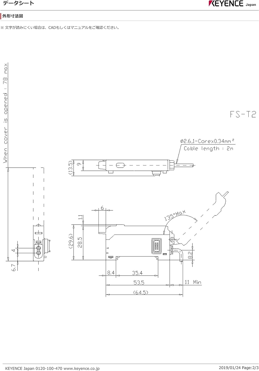
Figure 8.2: Dimensional drawing of the KEYENCE FS-T2, showing measurements in millimeters and cable specifications.
9. Warranty and Support
For warranty information, technical support, or service inquiries, please contact your local KEYENCE representative or visit the official KEYENCE website. Ensure you have your product model number (FS-T2) available when seeking support.
