1. Introduction
This manual provides essential instructions for the installation, operation, and maintenance of your HALLOMOTOR Ebike Brushless Controller and KT LCD3 Electric Bicycle Display. This system is designed for electric bicycles and supports 24V, 36V, and 48V configurations. Please read this manual thoroughly before installation and use to ensure proper function and safety.
Important Note: This controller is designed to work exclusively with motors that have Hall sensors. Please verify your motor type before proceeding with installation.
2. Product Overview
The HALLOMOTOR Ebike Controller and KT LCD3 Display system provides efficient power management and user interface for your electric bicycle. The controller manages motor speed, power output, and features regenerative braking and reverse functions. The KT LCD3 display offers real-time data such as speed, battery level, assist level, and trip distance, and is required to activate the regenerative function.

Image 2.1: HALLOMOTOR Ebike Controller and KT LCD3 Display. The image shows the black rectangular LCD3 display unit with a wired remote button panel, and a separate mounting bracket. The display shows digital readouts for speed, battery, and other parameters.
3. Package Contents
Verify that all items are present in your package:
- 1 x HALLOMOTOR 25A Brushless Controller (24V/36V Universal or 36V/48V Universal)
- 1 x KT LCD3 Electric Bicycle Display (24V/36V/48V Universal)
4. Specifications
| Feature | Specification |
|---|---|
| Rated Voltage | 24V/36V Universal or 36V/48V Universal |
| Minimum Voltage | DC30V/40V ±0.5V |
| Maximum Current | 25A ±1A |
| Speed Set | 1-4.2V |
| Brake Input | Low-Level |
| Controller Dimensions | Approximately 140mm x 68mm x 41mm |
| Controller Weight | Approximately 500g |
| MOSFETs | 9 |
| Special Features | Regenerative Function (requires KT LCD3 Display), Reverse Function |
5. Setup and Installation
Proper installation is crucial for the safe and efficient operation of your ebike system. If you are unsure about any steps, consult a qualified technician.
5.1 Controller Installation
Mount the controller in a secure location on your ebike, protected from water and physical damage. Ensure adequate ventilation for heat dissipation.
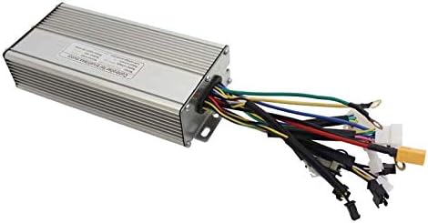
Image 5.1: HALLOMOTOR Ebike Controller Unit. The image displays the silver-colored, finned aluminum casing of the controller with multiple colored wires extending from one end, each terminated with a connector.
5.2 Wiring Diagram
Refer to the diagram below for correct wiring connections. Ensure all connections are secure and properly insulated to prevent short circuits.
- Battery Power Input: Connect the red wire to the positive (+) terminal of your battery and the black wire to the negative (-) terminal.
- Motor (3-Phase): Connect the blue, green, and yellow wires to the corresponding motor phase wires (MOTA A, B, C).
- Motor (Hall Sensor): Connect the Hall sensor wires (red, black, blue, green, yellow) to the motor's Hall sensor connector.
- Pedal Assist System (PAS): Connect the PAS sensor wires (red, black, yellow) to the PAS input.
- Throttle Speed Control: Connect the throttle wires (red, black, blue) to the throttle input.
- Brake Input: Connect the brake lever wires (yellow, black) to the brake input.
- LCD Control Panel: Connect the LCD display wires (red, blue, green, yellow, black) to the controller's LCD port.
- Speed Sensor: Connect the speed sensor wires (red, white, black) if applicable.
- Cruise Function: Connect cruise function wires (blue, black) if applicable.
- Light Power: Connect light power wires (black, yellow for LCD control; black, red for switch control) if applicable.
- Electric Lock: Connect electric lock wires (red, pink) if applicable.
- Reverse Function: Connect reverse function wires (white, black) if applicable.

Image 5.2: Detailed Controller Wiring Diagram. This diagram illustrates the various connectors and their corresponding wire colors for battery, motor (3-phase and Hall), PAS, throttle, brake, LCD, speed sensor, cruise, light power, electric lock, and reverse functions.
5.3 KT LCD3 Display Mounting
Mount the KT LCD3 display securely on your handlebars using the provided bracket. Ensure it is positioned for easy viewing while riding without obstructing your view of the road.
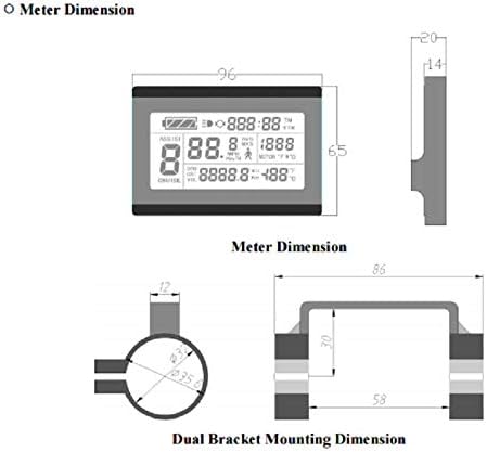
Image 5.3: KT LCD3 Display Dimensions and Dual Bracket Mounting Dimension. This image provides technical drawings showing the physical dimensions of the LCD display unit and the measurements for the dual bracket mounting system, including handlebar diameter compatibility.
6. Operating Instructions
The KT LCD3 display provides all necessary information and controls for your ebike system.
6.1 Display Content Overview
Familiarize yourself with the information presented on the LCD3 display:

Image 6.1: KT LCD3 Display Content Diagram. This diagram labels various sections of the LCD screen, including Battery Capacity, Backlights and Headlights Status, Brake Status, Vehicle Speed, Running Counter, 6Km/h Power Assist Push Function, Power Assist Ratio Gear and Cruise Function, Trip Distance or Real-time Battery Voltage, Environment Temperature, and Motor Operation Power or Motor Running Temperature.
- Battery Capacity Indicator: Shows the current charge level of your ebike battery.
- Backlights and Headlights Status: Indicates if the lights are on.
- Brake Status: Shows when the brakes are engaged.
- Vehicle Speed: Displays current riding speed.
- Running Counter: Tracks total operating time or similar metric.
- 6Km/h Power Assist Push Function: Activates a low-speed assist for walking the bike.
- Power Assist Ratio Gear and Cruise Function: Adjusts the level of motor assistance and indicates cruise control status.
- Trip Distance or Real-time Battery Voltage: Toggles between trip distance and real-time battery voltage.
- Environment Temperature: Displays ambient temperature.
- Motor Operation Power or Motor Running Temperature: Shows motor power output or temperature.
6.2 Basic Operation
- Power On/Off: Press and hold the power button on the display to turn the system on or off.
- Assist Level Adjustment: Use the '+' and '-' buttons to cycle through different levels of pedal assist.
- Regenerative Function: The regenerative braking function is activated through the KT LCD3 display settings. Consult the full LCD3 manual (if provided separately) for detailed instructions on enabling and configuring this feature.
- Reverse Function: If connected, the reverse function can be engaged via a dedicated switch or button, as configured with your system.
7. Maintenance
Regular maintenance ensures the longevity and reliability of your ebike controller and display.
- Keep Dry: Protect the controller and display from water and excessive moisture. While designed for outdoor use, direct exposure to heavy rain or submersion should be avoided.
- Clean Connections: Periodically check all electrical connections for corrosion or looseness. Ensure they are clean and secure.
- Cable Inspection: Inspect all cables for signs of wear, cuts, or damage. Replace damaged cables immediately.
- General Cleaning: Wipe the display and controller with a soft, damp cloth. Do not use harsh chemicals or abrasive cleaners.
8. Troubleshooting
If you encounter issues with your HALLOMOTOR ebike system, consider the following basic troubleshooting steps:
- System Not Powering On:
- Check battery charge level.
- Verify all power connections from the battery to the controller are secure.
- Ensure the display is properly connected to the controller.
- Motor Not Responding:
- Confirm the motor has Hall sensors, as this controller requires them.
- Check all motor phase and Hall sensor connections.
- Verify throttle and PAS connections.
- Ensure brake levers are not engaged, as they may cut motor power.
- Display Not Showing Correct Information:
- Check the connection between the display and the controller.
- Ensure speed sensor is correctly installed and connected (if applicable).
For more advanced troubleshooting or persistent issues, please contact HALLOMOTOR customer support or consult a professional ebike technician.
9. Warranty and Support
For information regarding product warranty, returns, or technical support, please refer to the documentation provided at the time of purchase or contact your seller directly. HALLOMOTOR is committed to providing quality products and support.
Manufacturer: Hallomotor
Model Number: 25A Controller +LCD3 DISPLAY


