1. Product Overview
The Marks Hardware 91A-RH Mortise Lock is a robust and durable locking mechanism designed for residential and commercial applications. This right-hand specific lock features a 2-1/2" backset, a solid brass 1" throw deadbolt, and a convenient rocker switch for locking or unlocking the outside knob. It is equipped with a 5-pin solid brass 1-1/4" cylinder and solid polished brass knobs.
- Marks Mortise Lock, Right Hand configuration.
- Manufactured by Marks Hardware Inc.
- Ultra durable construction for long-lasting performance.

2. Package Contents
Upon opening the package, please verify that all the following components are present:
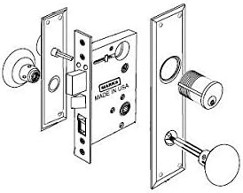
- Mortise Lock Body (1)
- Exterior Trim Plate with Knob and Cylinder (1)
- Interior Trim Plate with Knob (1)
- Cylinder Keys (Set of 2 or more)
- Spindle (2-piece threaded) (1)
- Strike Plate (1)
- Dust Box (1)
- Mounting Screws (Various sizes)
- Instruction Guide (This manual)
3. Specifications
Key technical specifications for the 91A-RH Mortise Lock:
| Feature | Specification |
|---|---|
| Model Name | 91A-RH |
| Brand | Marks Hardware |
| Lock Type | Pin Tumbler Mortise Lock |
| Handing | Right Hand |
| Backset | 2-1/2 inches |
| Deadbolt Throw | 1 inch (solid brass) |
| Cylinder | 5-pin solid brass 1-1/4 inch |
| Exterior Plate Dimensions | 2-3/4" x 10" |
| Interior Plate Dimensions | 2-1/4" x 7" |
| Material | Brass |
| Finish Type | Polished |
| Item Weight | 4.35 pounds |
| Product Dimensions | 11 x 5 x 4.25 inches |

4. Installation Guide
Proper installation is crucial for the optimal performance and security of your mortise lock. If you are unsure about any step, it is recommended to consult a professional locksmith or carpenter.
Tools Required:
- Drill
- Chisel
- Screwdriver Set
- Measuring Tape
- Pencil
- Wood Glue (optional, for shims)
Installation Steps:
- Prepare the Door: If installing on a new door, mark and mortise the door for the lock body, faceplate, and trim plates according to the lock's dimensions (refer to Figure 2). Ensure the mortise is deep enough for the lock body to sit flush.
- Install Mortise Lock Body: Slide the mortise lock body into the prepared mortise in the door edge. Secure it with the provided screws through the faceplate of the lock body. Ensure it is flush with the door edge.
- Install Spindle: Insert the two-piece threaded spindle through the square hole in the mortise lock body. Ensure it passes through the mechanism correctly.
- Attach Exterior Trim: Place the exterior trim plate over the spindle and cylinder hole. Insert the cylinder into its designated opening in the exterior plate and mortise body. Secure the cylinder with the set screw from the mortise body or interior side, if applicable.
- Attach Interior Trim: Place the interior trim plate over the spindle. Align the screw holes.
- Secure Trim Plates: Fasten the exterior and interior trim plates together using the long through-bolts or screws provided. Tighten them evenly to prevent binding.
- Install Knobs: Attach the knobs to the spindle. For the exterior knob, ensure the rocker switch is accessible and functional. Secure the knobs with their respective set screws.
- Install Strike Plate and Dust Box: On the door frame, mark the position for the strike plate based on the mortise lock's latch and deadbolt. Mortise the frame to accommodate the strike plate and dust box. Secure the strike plate with screws.
- Test Operation: Close the door and test the latch, deadbolt, and knob operation from both sides. Ensure smooth engagement and disengagement. Test the key operation and the rocker switch function.
5. Operating Your Mortise Lock
The Marks Hardware 91A-RH Mortise Lock is designed for straightforward operation:
- To Open from Outside (Unlocked): Turn the exterior knob. The latch bolt will retract, allowing the door to open.
- To Open from Outside (Locked): Insert the key into the cylinder and turn it to retract the deadbolt and/or unlock the exterior knob. Then turn the knob to retract the latch bolt.
- To Open from Inside: Turn the interior knob. The latch bolt will retract.
- To Lock from Outside: Use the key to extend the deadbolt. The exterior knob can also be locked by the internal rocker switch.
- To Lock from Inside: Extend the deadbolt by turning the interior thumbturn (if present) or by using the key. The rocker switch on the interior plate allows you to lock or unlock the exterior knob. When the rocker switch is in the locked position, the exterior knob will spin freely, preventing entry.
6. Maintenance
Regular maintenance ensures the longevity and smooth operation of your mortise lock:
- Cleaning: Wipe the exterior surfaces with a soft, damp cloth. Avoid abrasive cleaners or solvents that could damage the polished brass finish.
- Lubrication: Periodically apply a small amount of graphite lubricant or a silicone-based spray specifically designed for locks into the keyway and around moving parts of the latch and deadbolt. Do not use oil-based lubricants as they can attract dirt.
- Tighten Screws: Over time, screws may loosen. Periodically check and tighten all mounting screws on the trim plates and strike plate to ensure the lock remains securely installed.
- Check Alignment: Ensure the strike plate on the door frame remains aligned with the latch and deadbolt. Misalignment can cause binding or difficulty in locking.
7. Troubleshooting
If you encounter issues with your mortise lock, consider the following common problems and solutions:
- Key is Stiff or Hard to Turn:
- Apply graphite lubricant to the keyway.
- Check if the key is bent or damaged.
- Ensure the deadbolt is not binding against the strike plate. - Knob is Stiff or Not Turning:
- Check if the spindle is properly aligned and not bent.
- Ensure the trim plates are not overtightened, which can cause binding.
- Lubricate the internal mechanism of the lock body. - Latch or Deadbolt Not Retracting/Extending Fully:
- Verify that the mortise in the door is clear of debris.
- Check the alignment of the strike plate on the door frame.
- Ensure the lock body is securely fastened and not shifting. - Door Rattles When Closed:
- The strike plate might be too far from the latch. Adjust the strike plate or add shims behind it to reduce play. - Rocker Switch Not Functioning:
- Check for any obstructions or debris around the switch mechanism.
- Ensure the interior trim plate is properly seated and not interfering with the switch.
If problems persist after attempting these solutions, contact Marks Hardware customer support or a qualified locksmith.
8. Warranty and Support
For detailed information regarding the warranty coverage for your Marks Hardware 91A-RH Mortise Lock, please refer to the warranty card included with your purchase or visit the official Marks Hardware website. Warranty terms typically cover manufacturing defects under normal use.
For technical support, replacement parts, or further assistance, please contact Marks Hardware customer service directly. Have your model number (91A-RH) and purchase information ready when contacting support.
Marks Hardware Inc.
Contact information can typically be found on their official website or product packaging.


