
Usmile mbec6S
Matek X Class 12S PDB Power Distribution Board FCHUB-12S User Manual
Model: FCHUB-12S V2
1. Product Overview
The Matek FCHUB-12S V2 is a high-performance Power Distribution Board (PDB) specifically designed for X-class quadcopters. It supports a wide input voltage range from 8V to 60V (3-12S LiPo) and features integrated 5V 5A and 12V 4A regulators. This PDB includes a high-precision 440A current sensor, making it suitable for 4/5 inch carbon fiber FPV racing quadcopters.
Key features include:
- Wide input voltage range: 8~60V DC (3~12S LiPo)
- High continuous current handling: 4x70A continuous, 4x110A burst
- Integrated BECs: 5V 5A and 12V 4A outputs
- High-precision current sensor: 440A, 3.3V ADC, Scale 75
- Switchable 12V output for VTX, LED, etc.
- Compatible with flight controllers like H743-SLIM and F405-HDTE

Figure 1: Top and bottom view of the Matek FCHUB-12S V2 PDB. This image shows the component layout on both sides of the board, including the main power pads, BECs, and signal pads.
2. Specifications
| Feature | Specification |
|---|---|
| Input Voltage Range | 8~60V DC (3~12S LiPo) |
| Continuous Current | 4x70A (continuous), 4x110A (burst) |
| Current Sensor | 440A, 3.3V ADC, Scale 75 |
| BEC 5V Output | 5.1 +/- 0.1VDC, 5A continuous, 6A max |
| BEC 12V Output | 12.0 +/- 0.2VDC (Input >=12V), 4A continuous, 5A max |
| Switchable 12V Output (12VSW) | 12V ON/OFF switchable via PINIO, 2A constant support |
| BEC 3.3V Output | Linear Regulator, 500mA continuous |
| Mounting | 30.5 x 30.5mm, Φ3mm holes |
| Dimensions | 55 x 50 x 6 mm |
| Weight | 21g |

Figure 2: Dimensions of the FCHUB-12S V2 board, showing its compact size and standard mounting hole pattern.
3. Installation and Wiring
Proper installation and wiring are critical for the safe and effective operation of your FCHUB-12S V2. Always ensure power is disconnected before making any connections.
3.1 General Layout and Connections
The FCHUB-12S V2 provides dedicated pads for ESC power, signal, and telemetry, along with various regulated voltage outputs.
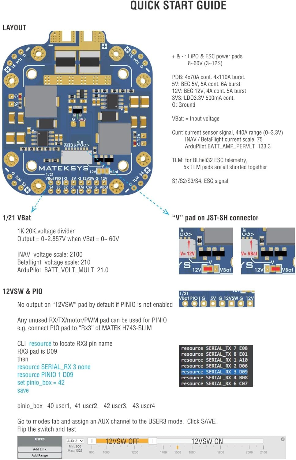
Figure 3: Quick Start Guide layout of the FCHUB-12S V2, detailing the various pads and their functions, including power inputs, ESC connections, and JST-SH connector pins.
- Input Power: Connect your 3-12S LiPo battery to the large positive (+) and negative (-) pads.
- ESC Connections: Solder ESC power wires to the 4x70A pads. Connect ESC signal wires to S1-S4 pads. Telemetry wires can be connected to the TLM pads.
- JST-SH 8pin Connector: This connector provides signals for current sensing (Curr), telemetry (TLM), ESC signals (S1-S4), and selectable voltage (V or VBat).
- Voltage Divider: A 1K:20K voltage divider is built-in for battery voltage monitoring. The "V" pad on the JST-SH connector can be configured for 12V or VBat voltage.
3.2 Wiring with Matek H743-SLIM Flight Controller
Follow this diagram for connecting the FCHUB-12S V2 to a Matek H743-SLIM flight controller. Ensure correct polarity for all power connections.

Figure 4: Detailed wiring diagram illustrating the connection of the FCHUB-12S V2 PDB to a Matek H743-SLIM flight controller, including ESCs and battery.
For Betaflight configuration with H743-SLIM:
- CLI command to locate RSSI pin name:
resource RSSI_ADC 1 none - Set ADC channel for battery:
resource ADC_BATT 1 C05 - Set VBat scale:
set vbat_scale = 210 - Save changes:
save
For INAV configuration:
- CLI command to get ADC to locate RSSI_ADC_channel:
resource ADC_RSSI 1 none - Set RSSI ADC channel:
set rssi_adc_channel = 0 - Set VBat ADC channel:
set vbat_adc_channel = 2 - Set VBat scale:
set vbat_scale = 2100 - Save changes:
save
For ArduPilot configuration:
- Set battery voltage pin:
BATT_VOLT_PIN 8 - Set battery voltage multiplier:
BATT_VOLT_MULT 21.0
3.3 Wiring with Matek F405-HDTE Flight Controller
Refer to this diagram for connecting the FCHUB-12S V2 to a Matek F405-HDTE flight controller. Pay close attention to the signal and power lines.

Figure 5: Wiring diagram showing the connection of the FCHUB-12S V2 PDB to a Matek F405-HDTE flight controller. This includes connections for ESCs and battery.
For Betaflight configuration with F405-HDTE:
- Set ADC channel for battery:
resource ADC_BATT 1 C00 - Set VBat scale:
set vbat_scale = 210 - Save changes:
save
For INAV configuration:
- Set RSSI ADC channel:
set rssi_adc_channel = 0 - Set VBat ADC channel:
set vbat_adc_channel = 3 - Set VBat scale:
set vbat_scale = 2100 - Save changes:
save
4. Operating Instructions
Once properly installed and wired, the FCHUB-12S V2 provides stable power distribution and regulated outputs for your drone components.
4.1 Power Distribution
The PDB efficiently distributes power from your LiPo battery to up to four ESCs, handling high continuous and burst currents. The integrated current sensor provides accurate current consumption data to your flight controller.
4.2 Regulated Outputs (BECs)
- 5V Output (5V pad): Provides a stable 5.1V DC output with up to 5A continuous current (6A max). This is suitable for powering your flight controller, receiver, GPS, and other 5V components. It features short-circuit tolerance and overcurrent protection.
- 12V Output (12V pad): Provides a stable 12.0V DC output with up to 4A continuous current (5A max), provided the input voltage is 12V or higher. If input voltage is below 12V, the output voltage will match the input. Ideal for powering VTX, cameras, and other 12V accessories. It also includes short-circuit tolerance and overcurrent protection.
- Switchable 12V Output (12VSW pad): This output can be turned ON/OFF via a PINIO signal from your flight controller, supporting a constant 2A. This is useful for controlling power to components like VTX or LEDs remotely.
- 3.3V Output: A linear regulator provides 3.3V DC with up to 500mA continuous current, typically used for specific sensors or peripherals requiring 3.3V.
Two LED indicators are present on the board to show the status of the 5V and 12V outputs.
5. Maintenance
The FCHUB-12S V2 is designed for durability, but proper care can extend its lifespan and ensure reliable performance.
- Regular Inspection: Periodically inspect the board for any signs of physical damage, loose solder joints, or corrosion.
- Cleanliness: Keep the board free from dust, dirt, and moisture. Use a soft brush or compressed air for cleaning. Avoid using liquid cleaners directly on the electronics.
- Environmental Protection: While robust, it is recommended to protect the PDB from direct exposure to water or extreme temperatures. Consider conformal coating for added moisture protection in humid environments.
- Connection Integrity: Ensure all wire connections are secure and properly insulated to prevent short circuits.
6. Troubleshooting
If you encounter issues with your FCHUB-12S V2, consider the following troubleshooting steps:
- No Power Output:
- Verify the input battery voltage is within the 8-60V range.
- Check all power connections for proper soldering and polarity.
- Inspect the 5V and 12V LED indicators on the board. If they are off, there might be an issue with the input power or the BECs.
- Incorrect Voltage Readings:
- Ensure the voltage divider settings in your flight controller firmware (Betaflight, INAV, ArduPilot) are correctly configured as per Section 3.2 or 3.3.
- Check the physical connection of the voltage sensing wire from the PDB to the flight controller.
- Inaccurate Current Readings:
- Verify the current sensor scale (Scale 75) is correctly set in your flight controller firmware.
- Ensure the current sensor signal wire is properly connected.
- Switchable 12V (12VSW) Not Working:
- Confirm that the PINIO feature is enabled and configured correctly in your flight controller firmware.
- Check the signal connection from the flight controller to the PDB's PINIO pad.
- Overheating:
- Ensure adequate airflow around the PDB.
- Verify that the current draw from connected components does not exceed the specified limits for the BECs or the main power distribution.
For further assistance, refer to the official Matek Systems website or contact their support channels.
Ask a question about this manual
Ask about setup, troubleshooting, compatibility, parts, safety, or missing instructions. Manuals+ will review the question and use this page’s manual context to help answer it.