1. Introduction
This manual provides essential information for the proper installation, operation, and maintenance of the Cisco 6509-E Switch Chassis. Designed for high-performance networking environments, this modular chassis supports a wide range of line cards and power supplies to meet diverse network requirements. Please read this manual thoroughly before attempting any installation or operation.
2. Safety Information
Always observe the following safety precautions to prevent injury and damage to the equipment:
- Ensure the chassis is properly grounded before connecting power.
- Do not operate the chassis with covers removed.
- Use only approved power cords and accessories.
- Disconnect all power before performing maintenance or installing/removing components.
- Heavy equipment: Use proper lifting techniques or assistance when moving the chassis due to its weight (approximately 150 pounds).
- Maintain adequate ventilation around the chassis to prevent overheating.
3. Product Overview
The Cisco 6509-E is a modular, 9-slot chassis designed for enterprise and service provider networks. It provides high-density port capacity and advanced services through various line cards and modules. The chassis supports redundant power supplies and fan trays for enhanced reliability.
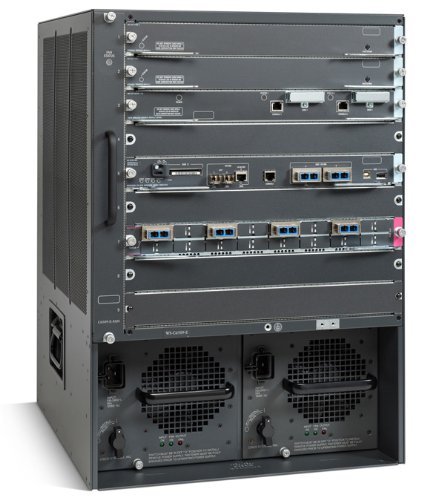
Figure 3.1: Front view of the Cisco 6509-E Switch Chassis. This image displays the full chassis, highlighting its modular design with multiple slots for line cards and two large bays at the bottom for power supply units, each with a fan grill.
3.1 Key Components
- Module Slots: 9 horizontal slots for various line cards, supervisor engines, and service modules.
- Power Supply Bays: Dedicated bays for redundant power supplies (e.g., AC or DC).
- Fan Tray: Provides cooling for the system components.
- Backplane: High-speed data path for communication between modules.
4. Setup and Installation
4.1 Site Preparation
- Ensure the installation site has adequate space for ventilation and maintenance access.
- Verify the floor can support the chassis weight (approx. 150 lbs / 68 kg) and any installed modules.
- Provide stable power sources with appropriate voltage and current capacity.
- Ensure proper grounding is available at the installation site.
4.2 Rack Mounting
The Cisco 6509-E is designed for standard 19-inch rack mounting. Use appropriate rack-mount kits (sold separately) and follow the instructions provided with the kit.
- Attach the rack-mount brackets to the chassis.
- Carefully slide the chassis into the rack, ensuring it is level and securely supported.
- Secure the chassis to the rack using the provided screws.
4.3 Module Installation
Install supervisor engines, line cards, and power supplies into their respective slots. Refer to the specific module's documentation for detailed installation procedures.
- Ensure power is disconnected before installing or removing modules.
- Align the module with the guide rails in the chassis slot.
- Gently push the module until it seats firmly in the backplane connector.
- Secure the module using the ejector levers or captive screws.
4.4 Power Connection
Connect the power cords to the power supply units and then to a grounded power outlet. For redundant power supplies, connect each to an independent power source if available.
5. Operating Instructions
5.1 Initial Power-Up
- After all modules are installed and power cords connected, turn on the power switches on the power supply units.
- Observe the system LEDs (e.g., SYS, STATUS) on the supervisor engine and individual modules. They should indicate successful power-up and initialization.
5.2 Console Access
Connect a console cable from your management workstation to the console port on the supervisor engine for initial configuration and management.
- Baud Rate: 9600
- Data Bits: 8
- Parity: None
- Stop Bits: 1
- Flow Control: None
5.3 Basic Configuration
Refer to the Cisco IOS Software Configuration Guides for detailed instructions on configuring the switch chassis, including IP addressing, VLANs, routing protocols, and security features. This manual focuses on hardware operation.
6. Maintenance
Regular maintenance ensures optimal performance and longevity of your Cisco 6509-E Switch Chassis.
6.1 Cleaning
- Periodically clean the fan trays and air vents to prevent dust buildup, which can impede airflow and cause overheating.
- Use a soft, lint-free cloth for exterior cleaning. Do not use liquid cleaners directly on the chassis.
6.2 Component Replacement
Hot-swappable components like power supplies and some line cards can be replaced without powering down the entire chassis. Always consult the specific module's documentation for hot-swap procedures.
- Power Supplies: Ensure the replacement power supply matches the specifications of the existing unit.
- Fan Trays: Replace fan trays if fan failure indicators are active or if excessive noise is detected.
7. Troubleshooting
This section provides basic troubleshooting steps for common issues. For complex problems, refer to Cisco's official documentation or contact technical support.
| Problem | Possible Cause | Solution |
|---|---|---|
| Chassis does not power on. | No power to power supply; faulty power supply; power switch off. | Verify power cord connection; check power outlet; ensure power supply switches are ON; test with known good power supply. |
| Module not recognized. | Module not fully seated; incompatible module; faulty module. | Reseat the module firmly; verify module compatibility with chassis and IOS version; try module in another slot or test with a known good module. |
| System overheating. | Blocked air vents; fan tray failure; high ambient temperature. | Clear obstructions from vents; check fan tray status LEDs; ensure adequate room ventilation; replace faulty fan tray. |
8. Specifications
| Feature | Detail |
|---|---|
| Model | WS-C6509-E |
| Brand | Cisco |
| Manufacturer | CISCO SYSTEMS - ENTERPRISE |
| Dimensions (L x W x H) | 18.19 x 17.52 x 24.49 inches (46.2 x 44.5 x 62.2 cm) |
| Weight | Approximately 150 Pounds (68 kg) |
| Number of Positions (Slots) | 9 |
| Mounting Type | Rack Mount |
| First Available Date | January 7, 2019 |
9. Warranty and Support
This product is offered as a renewed item. Please refer to the specific warranty terms provided by the seller or Amazon Renewed at the time of purchase. Typically, Amazon Renewed products are eligible for replacement or refund under the Amazon Renewed Guarantee if not satisfied with the purchase.
For technical support related to the Cisco 6509-E Switch Chassis, please consult Cisco's official documentation and support resources. For issues related to your renewed purchase, contact the seller or Amazon customer support.
Legal Disclaimer: We DO NOT accept RMAs or Returns for Non Defective Items. Any merchandise returned for repair and found NOT to be defective by our technicians will have a 25% restocking fee. There will be no exception to this policy. By placing a bid or order with us you have entered into a binding agreement that you acknowledge and accept our procedures. Additional warranty length is available, contact us directly for more details.


