1. Introduction
This manual provides essential information for the safe and effective operation of your Metravi XB-30 Fully-protected Digital Multimeter. The XB-30 is a versatile tool designed for measuring DC/AC voltage, DC current, resistance, and performing diode and continuity tests. It features a 1999-count backlit LCD display and overload protection up to 500V DC/AC RMS.
Please read this manual thoroughly before using the device to ensure proper handling and to prevent potential hazards.
2. Safety Information
Always adhere to the following safety precautions when using the Metravi XB-30 Digital Multimeter:
- Overload Protection: The device features overload protection of 500V DC/AC RMS. Do not exceed this rating.
- Category Rating: This multimeter conforms to CE, CAT-III 600V, and IEC 1010-1 standards. CAT-III is for measurements performed in the building installation at the distribution level.
- Inspect Before Use: Before each use, inspect the meter and test leads for any damage. Do not use if damaged.
- Proper Terminal Connection: Ensure test leads are connected to the correct input terminals for the desired measurement.
- Voltage Awareness: Be extremely cautious when working with voltages above 30V AC RMS, 42V peak, or 60V DC. These voltages pose a shock hazard.
- Do Not Operate in Explosive Environments: Do not use the meter in the presence of explosive gas, vapor, or dust.
- Battery Replacement: Replace batteries immediately when the low battery indicator appears to ensure accurate readings.
3. Product Overview
The Metravi XB-30 Digital Multimeter is designed for ease of use and durability. Key components include the LCD display, rotary function switch, and input terminals.

Figure 3.1: Front view of the Metravi XB-30 Digital Multimeter with test leads connected. The display shows '000', and the rotary switch is set to the OFF position. The input terminals for COM, VΩmA, and 10A are visible at the bottom.
3.1. Display
The 1999 (3 ½) count, 15mm backlit LCD provides clear digital readings. Indicators for units (V, A, Ω), polarity, low battery, and data hold will appear on the display.
3.2. Rotary Function Switch
This switch is used to select the desired measurement function and range. Ensure it clicks firmly into position for accurate operation.
3.3. Input Terminals
- COM: Common terminal for all measurements (black test lead).
- VΩmA: Input terminal for voltage, resistance, and current up to 200mA (red test lead).
- 10A: Input terminal for high current measurements up to 10A (red test lead).
4. Setup
4.1. Battery Installation
The Metravi XB-30 requires one 9V battery (included). Follow these steps to install or replace the battery:
- Ensure the multimeter is turned OFF and disconnect all test leads from any circuits.
- Locate the battery compartment cover on the back of the unit.
- Unscrew the retaining screw(s) and carefully remove the cover.
- Connect the 9V battery to the battery clip, observing correct polarity.
- Place the battery into the compartment and replace the cover, securing it with the screw(s).

Figure 4.1: Rear view of the Metravi XB-30 Digital Multimeter with the battery compartment open, showing the 9V battery slot and a GP Supercell 9V battery.
The multimeter features an Auto Power Off function to conserve battery life. It will automatically power off after a period of inactivity.
5. Operating Instructions
Before making any measurement, ensure the test leads are correctly inserted into the appropriate input terminals and the rotary switch is set to the desired function and range.
5.1. DC Voltage Measurement (0-200mV/2V/20V/200V/600V)
- Insert the red test lead into the VΩmA terminal and the black test lead into the COM terminal.
- Set the rotary switch to the desired DC Voltage (V=) range (e.g., 20V for measuring up to 20V). If the voltage is unknown, start with the highest range (600V) and decrease as needed.
- Connect the test probes across the component or circuit to be measured.
- Read the voltage value on the display. Observe polarity if indicated.
5.2. AC Voltage Measurement (0-200V/600V)
- Insert the red test lead into the VΩmA terminal and the black test lead into the COM terminal.
- Set the rotary switch to the desired AC Voltage (V~) range (e.g., 200V or 600V).
- Connect the test probes across the AC voltage source.
- Read the voltage value on the display.
5.3. DC Current Measurement (0-2000µA/20mA/200mA/10A)
Caution: Never connect the multimeter in parallel with a voltage source when measuring current. Always connect in series with the load.
- For currents up to 200mA, insert the red test lead into the VΩmA terminal. For currents up to 10A, insert the red test lead into the 10A terminal. The black test lead always goes into the COM terminal.
- Set the rotary switch to the appropriate DC Current (A=) range (e.g., 20mA, 200mA, or 10A).
- Open the circuit where current is to be measured and connect the multimeter in series.
- Read the current value on the display.
5.4. Resistance Measurement (0-200Ω/2KΩ/20KΩ/200KΩ/2MΩ)
Caution: Ensure the circuit is de-energized and all capacitors are discharged before measuring resistance.
- Insert the red test lead into the VΩmA terminal and the black test lead into the COM terminal.
- Set the rotary switch to the desired Resistance (Ω) range.
- Connect the test probes across the resistor or component.
- Read the resistance value on the display.
5.5. Diode Test
- Insert the red test lead into the VΩmA terminal and the black test lead into the COM terminal.
- Set the rotary switch to the Diode Test symbol (→|).
- Connect the red probe to the anode and the black probe to the cathode of the diode. A forward voltage drop (typically 0.5V to 0.8V for silicon diodes) will be displayed.
- Reverse the probes. The display should show "OL" (Open Loop) for a good diode.
5.6. Continuity Test
- Insert the red test lead into the VΩmA terminal and the black test lead into the COM terminal.
- Set the rotary switch to the Continuity Test symbol ()))).
- Connect the test probes across the circuit or component.
- If continuity exists (resistance below a certain threshold), the buzzer will sound, and the display will show a low resistance value. "OL" indicates an open circuit.
5.7. Battery Test (9V/1.5V)
This function allows for quick testing of 9V and 1.5V batteries under a light load.
- Insert the red test lead into the VΩmA terminal and the black test lead into the COM terminal.
- Set the rotary switch to the "9V BATT." or "1.5V BATT." position.
- Connect the red probe to the positive terminal and the black probe to the negative terminal of the battery.
- Read the voltage value on the display. A reading significantly below the nominal voltage indicates a weak or discharged battery.
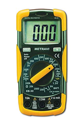
Figure 5.1: The Metravi XB-30 Digital Multimeter with test leads connected to a 9V battery, demonstrating the battery test function. The display shows a voltage reading.
5.8. Data Hold Function
Press the "HOLD" button to freeze the current reading on the display. Press it again to release the hold and resume live readings.
6. Maintenance
6.1. Cleaning
Wipe the meter casing with a damp cloth and a mild detergent. Do not use abrasives or solvents. Ensure the meter is completely dry before use.
6.2. Battery Replacement
Refer to Section 4.1 for detailed instructions on battery installation and replacement. Always use a fresh 9V battery when the low battery indicator appears on the display.
7. Troubleshooting
If the multimeter does not function correctly, consider the following common issues:
- No Display/Faint Display: Check the battery. Replace if necessary.
- "OL" on Display: This typically indicates an over-range condition (measurement exceeds the selected range) or an open circuit (e.g., during continuity or resistance tests). Select a higher range or check the circuit connection.
- Incorrect Readings:
- Ensure test leads are securely connected to the correct input terminals.
- Verify the rotary switch is set to the appropriate function and range.
- Check the battery level. Low battery can affect accuracy.
- No Continuity Beep: Ensure the rotary switch is set to the continuity function and the circuit is not open.
If problems persist, contact customer support as detailed in Section 9.
8. Specifications
| Feature | Specification |
|---|---|
| Display | 1999 (3 ½) Count, 15mm Backlit LCD |
| Overload Protection | 500V DC/AC RMS |
| DC Voltage Ranges | 0-200mV, 2V, 20V, 200V, 600V |
| AC Voltage Ranges | 0-200V, 600V |
| DC Current Ranges | 0-2000µA, 20mA, 200mA, 10A |
| Resistance Ranges | 0-200Ω, 2KΩ, 20KΩ, 200KΩ, 2MΩ |
| Battery Test | 9V, 1.5V |
| Diode Test | Yes |
| Continuity Test | Yes (with buzzer) |
| Data Hold | Yes |
| Auto Power Off | Yes |
| Safety Conformance | CE, CAT-III 600V, IEC 1010-1 |
| Power Source | 1 x 9V Battery (included) |
| Dimensions (L x W x H) | 15 x 7 x 4.8 Centimeters |
| Item Weight | 500 g |
9. Warranty and Support
Metravi Instruments provides a 1-year warranty against manufacturing defects for the XB-30 Digital Multimeter.

Figure 9.1: Metravi warranty and contact information, indicating a 1-year warranty against manufacturing defects and contact details for support.
9.1. Customer Support
For usage issues, product issues, replacements, or warranty claims, please contact Metravi customer support:
- Email: online_sales@metravi.com
- SMS / WhatsApp: 9073384641
Please have your product model number (XB-30) and purchase details ready when contacting support.


