1. Introduction
This instruction manual provides essential information for the safe and efficient installation, operation, and maintenance of the HVAC Parts Riello Control Box, model numbers 3001157, C7001029, and 530SE. This device functions as an oil primary relay and ignitor combo, designed for specific heating system applications. Please read this manual thoroughly before attempting any installation or operation.
2. Safety Information
WARNING: Improper installation, adjustment, alteration, service, or maintenance can cause property damage, injury, or death. Read the installation, operating, and maintenance instructions thoroughly before installing or servicing this equipment.
- Installation and servicing must be performed by a qualified service technician.
- Disconnect all power to the heating system before installing or servicing the control box.
- Ensure all wiring connections comply with local and national electrical codes.
- Do not operate the heating system if any part is submerged in water. Immediately call a qualified service technician to inspect the system and replace any part of the control system that has been submerged.
- This control box is designed for specific applications. Verify compatibility with your heating system before installation.
3. Product Overview
The Riello Control Box (models 3001157, C7001029, 530SE) is a critical component in oil-fired heating systems, integrating the functions of an oil primary relay and an ignitor. It manages the ignition sequence, monitors flame presence, and ensures safe shutdown in case of ignition failure or flame loss.

Figure 3.1: Front and top view of the Riello Control Box. This image displays the main body of the control box, showing its compact, rectangular white casing with two black electrical connectors protruding from one side. The top surface has embossed text, likely indicating model numbers and specifications.
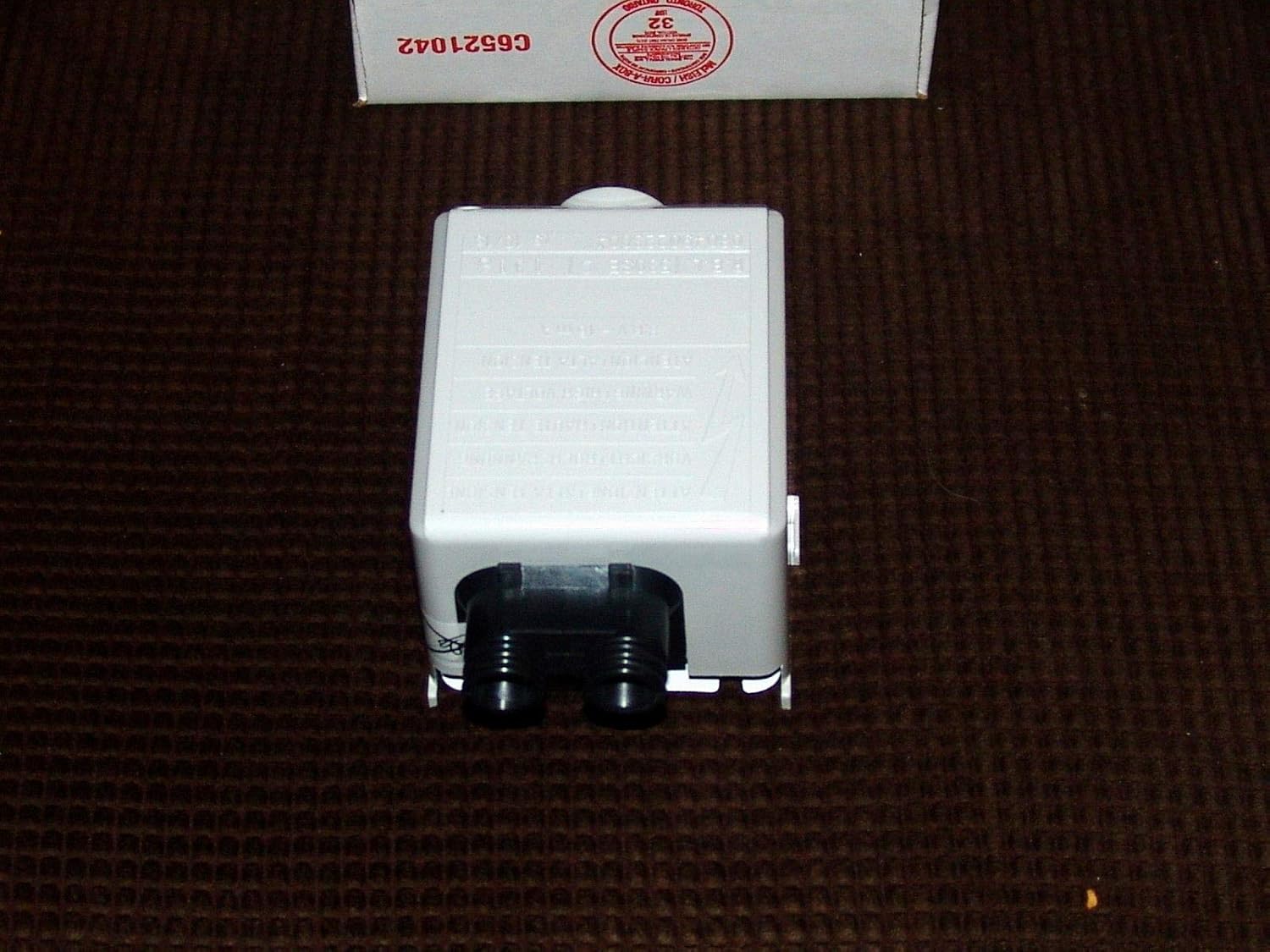
Figure 3.2: Rear view of the Riello Control Box. This perspective highlights the two black electrical connectors at the back of the unit, designed for secure wiring connections. The main body of the control box is visible, resting on a dark, textured surface.

Figure 3.3: Wiring diagram for the Riello Control Box. This image shows the underside of the control box, revealing a detailed wiring schematic printed on a white label. The diagram illustrates connections for motor, capacitor, thermostats, lock-out lamp, valve, and power supply (L and N), with color codes for different wire types (Brown, White, Blue, Black).
4. Setup and Installation
Before You Begin: Ensure all power to the heating system is disconnected at the main circuit breaker. Verify that the new control box matches the specifications of the old unit or is compatible with your heating system.
- Power Disconnection: Turn off the main power supply to the furnace or boiler. Confirm power is off using a voltage tester.
- Access Old Control Box: Locate and carefully remove the cover or access panel to expose the existing control box.
- Disconnect Wiring: Label all wires connected to the old control box before disconnecting them. Take a photograph for reference if necessary. Carefully disconnect each wire.
- Remove Old Unit: Unmount the old control box from its position.
- Mount New Unit: Securely mount the new Riello Control Box in the same location as the old unit.
- Connect Wiring: Refer to the wiring diagram (Figure 3.3) and your labels to connect all wires to the new control box. Ensure connections are tight and secure. Pay close attention to line (L), neutral (N), motor, valve, and thermostat connections.
- Verify Connections: Double-check all wiring against the diagram and your labels to prevent misconnections.
- Restore Power: Once all connections are verified and the system is reassembled, restore power to the heating system.
Consult a qualified HVAC technician if you are unsure about any step of the installation process.
5. Operating Instructions
The Riello Control Box operates automatically as part of your oil-fired heating system. Its primary function is to manage the burner's ignition and operation cycle.
Normal Operation Sequence:
- Call for Heat: When the thermostat calls for heat, the control box receives a signal.
- Pre-purge (if applicable): Some systems may have a pre-purge cycle before ignition.
- Ignition: The control box activates the ignitor to create a spark and opens the oil valve to allow fuel flow.
- Flame Detection: A flame sensor (photocell) monitors for the presence of a flame.
- Run Cycle: If a flame is detected within the safety timing, the ignitor deactivates, and the burner continues to operate until the call for heat ends.
- Post-purge (if applicable): Some systems may have a post-purge cycle after the burner shuts off.
Lockout Condition:
If the control box fails to establish a flame within the specified safety timing, or if the flame is lost during operation, the control box will enter a "lockout" state. This is a safety feature to prevent the accumulation of unburned fuel. A lockout condition is typically indicated by a red reset button or indicator light on the control box or furnace.
To reset a lockout, press and hold the reset button (if present) for approximately 1-2 seconds, then release. Do not repeatedly press the reset button without addressing the underlying issue, as this can lead to dangerous conditions.
6. Maintenance
The Riello Control Box itself generally requires no routine maintenance. However, it is part of a larger heating system that does require regular professional servicing.
- Annual System Check: Have your entire oil-fired heating system inspected and serviced annually by a qualified HVAC technician. This includes checking the burner, nozzle, electrodes, oil filter, and flue.
- Cleanliness: Ensure the area around the control box and burner is kept clean and free of dust, debris, and flammable materials.
- Wiring Integrity: During annual service, the technician should inspect all wiring connections for tightness and signs of wear or damage.
Do not attempt to open or repair the control box yourself. Refer all servicing to qualified personnel.
7. Troubleshooting
This section provides guidance for common issues. For complex problems, always contact a qualified service technician.
| Problem | Possible Cause | Solution |
|---|---|---|
| Burner does not ignite (control box in lockout) |
|
|
| Burner ignites but quickly shuts off (locks out) |
|
|
| No power to control box |
|
|
8. Specifications
| Feature | Detail |
|---|---|
| Model Numbers | 3001157, C7001029, 530SE |
| Part Number | alp171218-11 |
| Function | Oil Primary Relay & Ignitor Combo |
| Item Weight | 14 ounces |
| Package Dimensions | 6.02 x 4.41 x 4.33 inches |
| Batteries Required | No |
9. Warranty and Support
For warranty information and technical support, please refer to the documentation provided with your original heating system or contact the manufacturer of the Riello Control Box directly. Keep your purchase receipt for warranty claims.
For service or further assistance, it is recommended to contact a qualified HVAC professional.


