1. Introduction
The Walfront T7 Multifunction Transistor Tester is a versatile diagnostic instrument designed for electronic enthusiasts and professionals. It features a full-color graphic display and is capable of automatically identifying and measuring various electronic components, including triodes, diodes, resistors, capacitors, inductors, thyristors, field-effect transistors (FETs), regulators, light-emitting diodes (LEDs), and performing infrared decoding. This device includes a built-in rechargeable lithium battery for portable use.
2. Safety Information
Please read and understand all safety instructions before operating the device. Failure to follow these instructions may result in injury or damage to the device.
- Discharge Capacitors: Always discharge any capacitors before connecting them to the tester. Charged capacitors can cause damage to the tester and pose a shock hazard.
- Power Source: Use only the provided USB cable for charging the internal lithium battery.
- Operating Environment: Operate the tester in a dry environment, away from moisture and extreme temperatures.
- Component Voltage: The tester is designed for low-voltage component testing. Do not connect components from high-voltage circuits.
- Inspection: Before each use, inspect the tester and cables for any signs of damage. Do not use if damaged.
3. Package Contents
Verify that all items listed below are present in your package:
- 1 x Walfront T7 Transistor Tester
- 1 x USB Charging Cable
- 1 x Set of Red, Yellow, Green Test Wires (with clips)
- 3 x Test Pins
- 2 x Capacitors (for testing/calibration, if included)
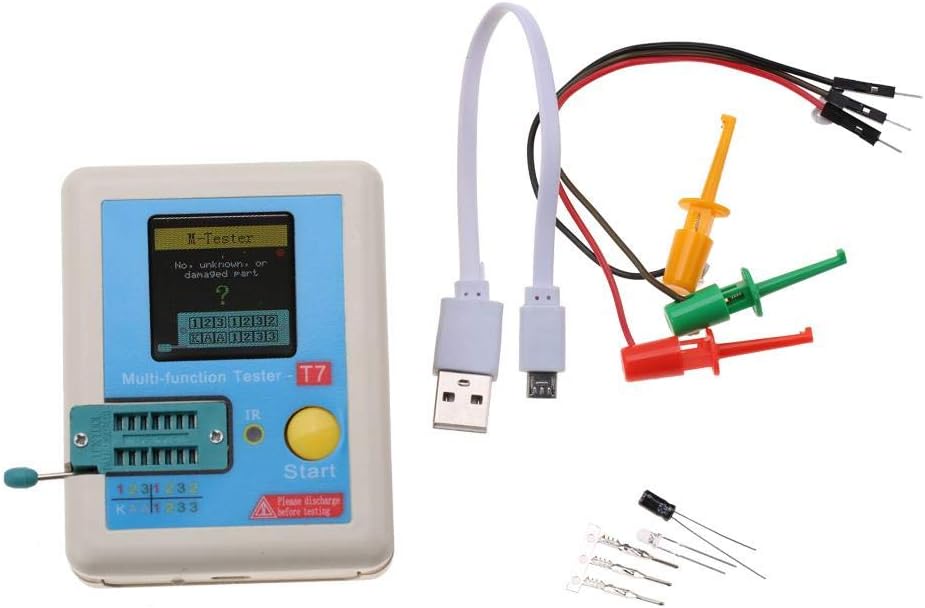
Image 3.1: Walfront T7 Transistor Tester with USB cable, test wires, and additional components.
4. Product Overview
The Walfront T7 features a compact design with a full-color graphic display for clear readings. Key components include the Zero Insertion Force (ZIF) socket for component testing, an infrared (IR) receiver, and a 'Start' button for initiating tests.

Image 4.1: Front view of the Walfront T7 Tester, highlighting the display and ZIF socket.
Key Features:
- Automatic Component Detection: Identifies and measures various components automatically.
- Full-Color Graphic Display: Provides clear and detailed measurement results.
- Self-Test with Automatic Calibration: Ensures accuracy and convenient operation.
- Infrared (IR) Decoding Support: Capable of decoding IR signals.
- Infrared Waveform Display: Visual representation of IR signals.
- Built-in Rechargeable Lithium-Ion Battery: Offers portability and long battery life.
- Automatic Shutdown: Configurable timeout setting to conserve battery.
5. Setup
5.1 Charging the Battery
The Walfront T7 includes a built-in rechargeable lithium-ion battery. Before initial use, or when the battery indicator shows low charge, connect the tester to a USB power source using the provided USB cable.
- Locate the Micro-USB port on the side of the tester.
- Connect the small end of the USB cable to the tester's Micro-USB port.
- Connect the standard USB end to a USB wall adapter (not included) or a computer's USB port.
- The display will indicate charging status. Allow sufficient time for a full charge.

Image 5.1: Side view of the tester, showing the Micro-USB charging port.
5.2 Connecting Components
Components can be connected using the ZIF (Zero Insertion Force) socket or the provided test wires/pins.
- ZIF Socket: Lift the lever on the ZIF socket, insert the component leads into the desired pins (labeled 1, 2, 3), and then lower the lever to secure the component. Ensure good contact.
- Test Wires/Pins: For larger components or in-circuit testing (with caution), use the provided test wires with clips or pins. Connect the clips/pins to the component leads and then connect the other end of the wires to the corresponding pins (1, 2, 3) on the ZIF socket or dedicated test points if available.

Image 5.2: Close-up of the ZIF socket, showing pin assignments.
6. Operating Instructions
6.1 Powering On and Self-Test
Press the yellow 'Start' button to power on the device. The tester will perform a brief self-test and calibration sequence. Ensure no component is connected during the self-test for accurate calibration.

Image 6.1: The tester performing a self-test with automatic calibration.
6.2 Component Testing
After the self-test, the tester is ready for component measurement.
- Prepare Component: Ensure the component is discharged (especially capacitors) and its leads are clean.
- Connect Component: Insert the component leads into the ZIF socket (pins 1, 2, 3) or connect via test wires. The tester will automatically detect the component type and pinout.
- Initiate Test: Press the yellow 'Start' button. The tester will perform the measurement.
- Read Results: The full-color graphic display will show the component type, pin configuration, and measured values (e.g., resistance, capacitance, inductance, transistor gain, diode forward voltage).
Examples of Component Measurements:
- Transistors (BJT, FET): Identifies NPN/PNP, N-channel/P-channel, measures hFE, V_f, C_gs, etc.
- Diodes: Identifies diode type, measures forward voltage drop. Supports automatic detection of Zener diodes (0.01-30V).
- Resistors: Measures resistance value.
- Capacitors: Measures capacitance, ESR (Equivalent Series Resistance), and V_loss.
- Inductors: Measures inductance value.
- Thyristors/TRIACs: Identifies type and gate voltage.
- Infrared (IR) Decoding: Point an IR remote control at the IR receiver and press a button to decode the signal and display the waveform.

Image 6.2: The tester's capability for automatic detection of Zener diodes.
6.3 Automatic Shutdown
The device features an automatic shutdown function to conserve battery power. The timeout period can typically be configured in the device settings (refer to on-screen menus if available) or is set to a default duration.
7. Maintenance
7.1 Cleaning
To maintain the tester's performance and appearance:
- Wipe the exterior with a soft, dry cloth.
- Do not use abrasive cleaners, solvents, or harsh chemicals.
- Keep the ZIF socket free from dust and debris. Use compressed air if necessary.
7.2 Battery Care
For optimal battery life:
- Charge the battery regularly, avoiding complete discharge for extended periods.
- If storing the device for a long time, charge it to approximately 50% every few months.
- Do not expose the device to extreme temperatures.
8. Troubleshooting
If you encounter issues with your Walfront T7 tester, refer to the following common problems and solutions:
| Problem | Possible Cause | Solution |
|---|---|---|
| Device does not power on. | Low or depleted battery. | Connect the device to a USB power source and charge the battery. |
| "No, unknown, or damaged part" message. | Component not properly connected, damaged component, or component outside measurement range. | Ensure component leads are clean and securely inserted into the ZIF socket. Try testing a known good component. Verify component type is supported. |
| Inaccurate readings. | Tester needs calibration, or component leads are dirty/corroded. | Perform a self-test without any component connected to recalibrate. Clean component leads. Ensure capacitors are fully discharged before testing. |
| Display is dim or flickering. | Low battery. | Charge the battery. |
9. Specifications
| Feature | Specification |
|---|---|
| Main Color | Blue (referring to the panel color) |
| Scanning Range | 0.1 MHz |
| Operating Voltage | 3.7 V (Internal Lithium-Ion Battery) |
| Display | 160 x [resolution not fully specified, assumed graphic display] |
| Battery Capacity | 300 mA (Lithium-Ion) |
| Item Weight | Approx. 115g (4.1 oz) |
| Product Dimensions | 2.76 x 1.18 x 3.54 inches |
| Automatic Diode Detection | 0.01-30V |
10. Warranty and Support
Specific warranty details for the Walfront T7 Multifunction Transistor Tester are not provided in this manual. For warranty information, technical support, or service inquiries, please contact Walfront customer service directly or refer to the product's purchase documentation.
You may also visit the official Walfront store on Amazon for additional product information and support resources: Walfront Store