Introduction
This manual provides comprehensive instructions for the CHANZON 400 Tie-Point Solderless Breadboard Kit (BB-801). This kit includes three universal PCB breadboards designed for rapid prototyping of electronic circuits without soldering. It is ideal for small DIY projects, Arduino, Raspberry Pi, and other microcontroller-based experiments.
Product Overview and Key Features
The CHANZON BB-801 breadboard offers a reliable platform for circuit development. Each board features 400 tie points, providing ample space for various components.
- Solderless Design: Allows for quick assembly and modification of circuits without the need for soldering, making it reusable and ideal for learning and experimentation.
- Tight Spring Connections: Equipped with high-quality metal springs under each tie point, ensuring secure and consistent electrical connections for all components.
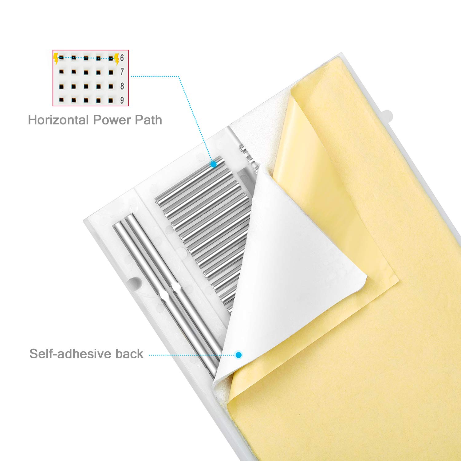
- Horizontal Power Paths: Each horizontal power path includes 5 insert points, facilitating easy connection of DIP components, sensors, transistors, capacitors, resistors, and other devices.
- Expandable Design: Multiple breadboards can be connected together using the integrated bolts on the side, allowing for larger and more complex circuit designs.
- Removable Power Rails: Two removable power rails are located on both sides of the PCB, providing dedicated power and ground connections for convenience.
- Self-Adhesive Backing: Features a self-adhesive tape on the back for secure mounting to work surfaces or project enclosures.
- Compatibility: Fully compatible with common development platforms such as Raspberry Pi and Arduino, as well as various electronic components including LEDs, screw terminals, Dupont wires, and ICs.
Product Visuals


Setup Guide
Setting up your CHANZON breadboard is straightforward. Follow these steps to prepare your prototyping environment:
- Unpack: Carefully remove the breadboards from their packaging.
- Inspect: Before use, visually inspect each breadboard for any physical damage or manufacturing defects.
- Power Rails: The breadboards come with two removable power rails. These can be detached if not needed for your specific project or reattached as required. They provide convenient access to power (red line, typically +V) and ground (blue line, typically GND) connections.
- Adhesive Backing (Optional): If you wish to secure the breadboard to a surface, peel off the protective film from the self-adhesive tape on the back and press the breadboard firmly onto your desired surface.
- Expanding Your Workspace (Optional): For larger projects, multiple breadboards can be interconnected. Align the side edges of two breadboards and use the integrated male/female connectors (bolts) to snap them together securely.
Operating Instructions
Using the solderless breadboard for circuit prototyping involves understanding its internal connections and proper component placement.
Understanding Breadboard Connections:
- Main Tie Points (Component Area): The central area of the breadboard consists of rows of 5 interconnected holes (e.g., A1-E1, F1-J1). Components inserted into these 5 holes in the same row are electrically connected. Each row is isolated from adjacent rows.
- Power Rails (Bus Strips): The long vertical strips on the sides (marked with red for positive and blue for negative/ground) are typically used for power distribution. All holes along a single power rail are interconnected.
Building a Circuit:
- Component Insertion: Gently push the leads of components (resistors, LEDs, ICs, etc.) into the desired holes. Ensure the leads are straight to avoid bending or damaging the internal springs. The tight spring connections of CHANZON breadboards ensure a secure fit.
- Connecting Components: Use jumper wires to connect different sections of the breadboard. For example, to connect a component in row 1 to a component in row 5, use a jumper wire between any hole in A1-E1 and any hole in A5-E5.
- Powering Your Circuit: Connect your power supply (e.g., Arduino 5V, external power supply) to the power rails. Typically, the positive voltage connects to the red rail and ground to the blue rail. Then, use jumper wires to bring power and ground from these rails to the components in your circuit.
- Testing: After assembling your circuit, carefully review all connections before applying power. Use a multimeter to check continuity and voltage levels as needed.
Maintenance
Proper maintenance ensures the longevity and reliability of your CHANZON breadboards.
- Cleanliness: Keep the breadboard clean and free from dust, debris, and solder residue. Use a soft, dry brush or compressed air to remove particles. Avoid using liquids or harsh chemicals.
- Component Insertion/Removal: Always insert and remove components gently and straight to prevent bending or damaging the internal spring clips. Avoid forcing oversized component leads into the holes.
- Storage: Store breadboards in a dry, cool environment, away from direct sunlight and extreme temperatures. If possible, keep them in their original packaging or a protective container to prevent dust accumulation and physical damage.
- Avoid Overloading: While the breadboard is designed for low current applications (<5A), avoid drawing excessive current through individual connections, as this can degrade the internal springs over time.
Troubleshooting
If you encounter issues while using your breadboard, consider the following common problems and solutions:
| Problem | Possible Cause | Solution |
|---|---|---|
| Component feels loose or connection is intermittent. | Bent component lead, worn-out internal spring, or incorrect lead size. | Ensure component leads are straight. Try inserting the component into a different hole. If the issue persists, the internal spring might be damaged; consider using a different section of the breadboard or a new breadboard. Use 20-29 AWG (0.3-0.8mm) jumper wires for optimal fit. |
| Circuit not functioning as expected. | Incorrect wiring, faulty component, insufficient power, or short circuit. | Double-check all connections against your circuit diagram. Test individual components. Verify power supply voltage and current. Use a multimeter to check for continuity and shorts. |
| Difficulty inserting or removing components. | Component leads are too thick or bent, or the breadboard holes are new/tight. | Ensure leads are straight and within the recommended 20-29 AWG (0.3-0.8mm) range. For new, tight holes, gently insert and remove a standard jumper wire a few times to loosen the connection slightly. Avoid excessive force. |
Product Specifications
| Feature | Detail |
|---|---|
| Model Number | BB-801 (3PCB-MBB-400) |
| Tie Points | 400 |
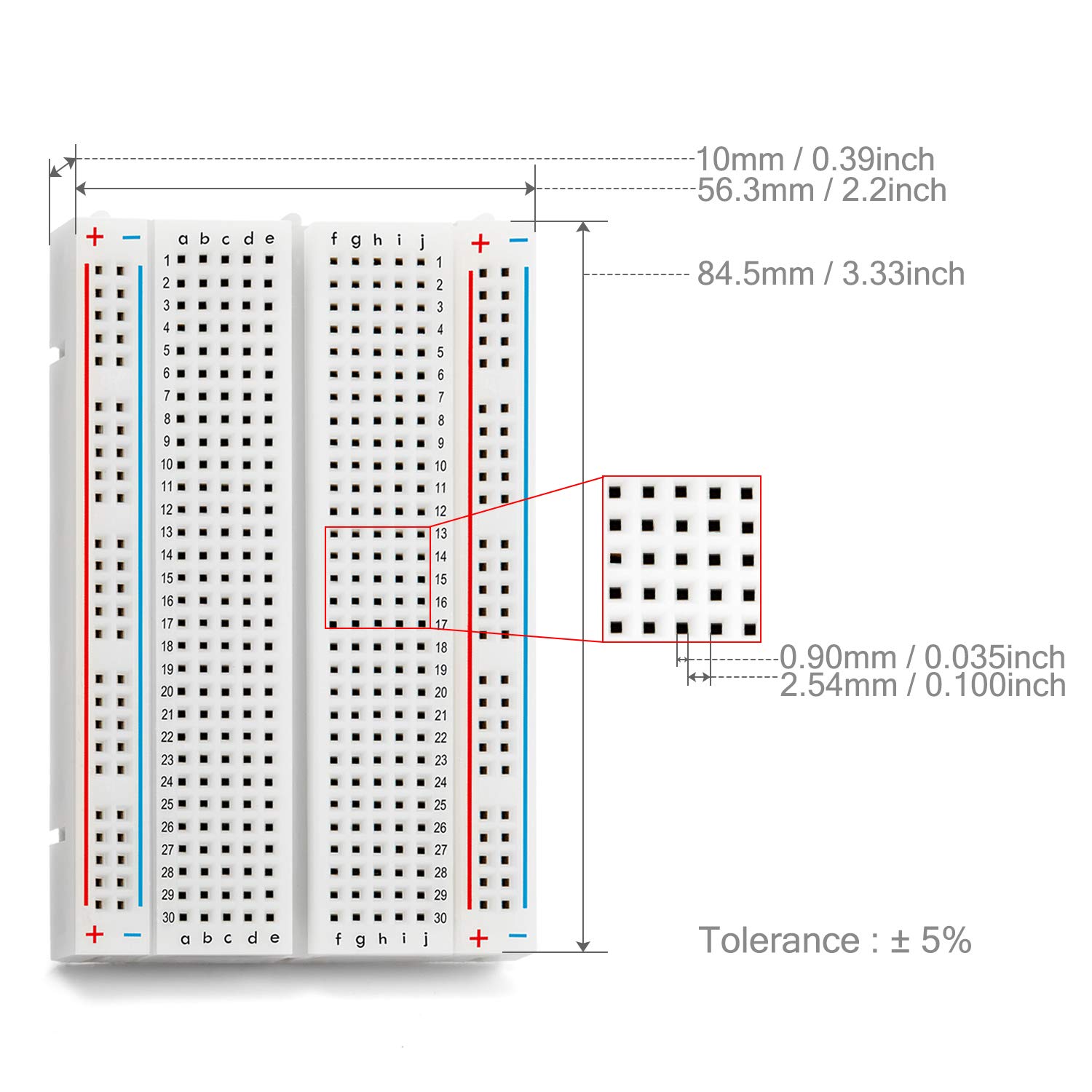
| Hole Diameter | 0.9 mm |
| Hole Pitch | 2.54 mm / 0.1 inches |
| Thickness | 10 mm |
| Dimensions (L x W x H) | 84.5 mm x 56.3 mm x 10 mm (3.33 x 2.2 x 0.39 inches) |
| Material | ABS Plastic (single-sided) |
| Voltage Rating | Up to 300V |
| Current Rating | Less than 5A |
| Compatible Wire Gauge | 20-29 AWG (0.3-0.8mm) |
| Kit Contents | 3 pieces of 400 pin breadboards |
Warranty and Customer Support
CHANZON is committed to providing high-quality products and excellent customer service.
Warranty Information:
For specific warranty details regarding your CHANZON 400 Tie-Point Solderless Breadboard Kit, please refer to the product listing on the retailer's website or contact CHANZON customer service directly. Our products are designed for durability and performance in electronic prototyping applications.
Customer Service:
Our electronic customer service team is available 24/7 to assist with any inquiries, technical support, or issues you may encounter with your product. Please reach out to us through the retailer's messaging system or visit the official CHANZON website for contact information.
For more information and to explore other CHANZON products, please visit the Official CHANZON Store on Amazon.


