1. Introduction and Overview
This manual provides essential information for the safe and effective use of your YESWELDER MIG Welding Gun Torch Stinger. This 100 Amp, 10-foot (3m) MIG gun is designed as a direct replacement for Hobart H-10 (part numbers 195957 and H100S2-10/245924) welding guns. It is fully interchangeable and compatible with various Hobart Handler models, including 130XL, 135, 140, 175, 187, and AutoArc XLT142 and XLT182 welders that utilize a direct-connect cable. The torch is designed to use Miller M-series MIG gun consumables and is ready to feed .030-.035 inch diameter welding wire.

Figure 1: YESWELDER MIG Welding Gun Torch Stinger
2. Safety Information
WARNING: Welding can be hazardous. Always follow safety precautions to prevent serious injury or death.
- Electric Shock: Can kill. Do not touch live electrical parts. Wear dry welding gloves and protective clothing. Insulate yourself from work and ground.
- Fumes and Gases: Can be hazardous to your health. Keep your head out of the fumes. Use enough ventilation or exhaust at the arc to keep fumes and gases away from the breathing zone.
- Arc Rays: Can burn eyes and skin. Wear a welding helmet with a proper shade of filter to protect your face and eyes. Wear appropriate eye protection with side shields when not welding. Wear protective clothing made from durable, flame-resistant material.
- Fire and Explosion: Welding sparks and hot metal can cause fires or explosions. Keep flammable materials away from the welding area. Have a fire extinguisher readily available.
- Hot Parts: Can cause severe burns. Do not touch hot parts with bare hands. Allow the equipment to cool before handling or performing maintenance.
3. Product Components
The YESWELDER MIG Welding Gun Torch consists of several key components designed for efficient and reliable welding. Understanding these parts is crucial for proper setup and maintenance.
- Torch Handle: Ergonomically designed for comfortable grip and control during welding.
- Trigger: Activates the welding process, controlling wire feed and gas flow.
- Cable: A 10-foot (3m) high-quality cable connects the torch to the welding machine, providing power and gas.
- Anti-Breaking Spring: Located at the cable connection point to prevent kinking and damage.
- Gas Nozzle: Directs shielding gas to the weld puddle.
- Contact Tip: Electrically conductive tip that transfers current to the welding wire.
- Gas Diffuser: Distributes shielding gas evenly around the contact tip.
- Wire Connectors: Female spade terminals with hard plastic covers for secure electrical connection to the welder.

Figure 2: Detachable Components (Gas Nozzle, Contact Tip, Gas Diffuser)

Figure 3: Internal Connection Details and Electrical Terminals

Figure 4: Ergonomic Handle and High-Quality Cable Construction
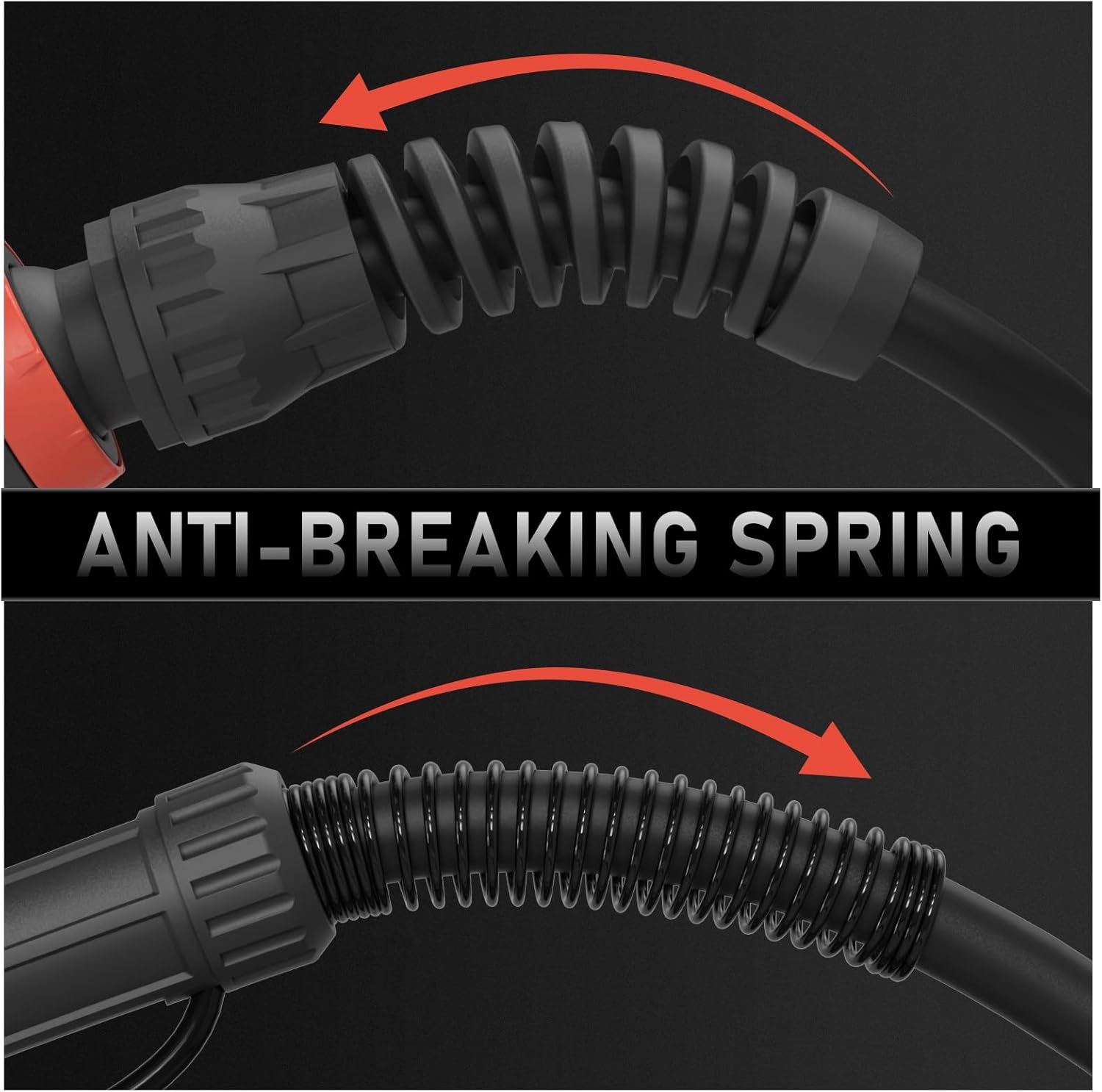
Figure 5: Anti-Breaking Spring for Cable Protection
4. Setup Instructions
Follow these steps to properly set up your MIG welding gun:
- Connect to Welder: Ensure your welding machine is turned off and unplugged. Connect the direct-connect cable of the MIG gun to the corresponding port on your Hobart Handler welder. Secure the connection firmly.
- Electrical Connections: Connect the female spade terminals from the MIG gun to the appropriate electrical terminals inside your welder, typically for the trigger circuit. Ensure these connections are secure and insulated with their hard plastic covers.
- Install Consumables:
- Screw the gas diffuser onto the torch body.
- Thread the correct size contact tip (.030-.035 inch) into the gas diffuser.
- Slide the gas nozzle over the contact tip and diffuser, ensuring it clicks into place or is securely tightened, depending on the nozzle type.
- Load Welding Wire: Feed the appropriate diameter welding wire (.030-.035 inch) through the welder's wire feeder mechanism and into the MIG gun liner until it exits the contact tip. Adjust wire tension as per your welder's instructions.
- Connect Shielding Gas: If using shielding gas, connect the gas hose from your regulator to the gas inlet on your welding machine. Ensure all gas connections are tight to prevent leaks.
5. Operating Instructions
Once the MIG gun is properly set up, you can begin welding. Always wear appropriate personal protective equipment (PPE) including a welding helmet, gloves, and protective clothing.
- Power On: Turn on your welding machine and gas supply (if applicable).
- Set Parameters: Adjust the voltage and wire feed speed settings on your welder according to the type and thickness of the material you are welding, and the welding wire being used.
- Initiate Arc: Position the contact tip approximately 3/8 to 1/2 inch from the workpiece. Press the trigger on the MIG gun to start the wire feed and gas flow, initiating the welding arc.
- Maintain Arc: Maintain a consistent arc length and travel speed. Move the torch steadily along the joint, ensuring proper penetration and bead formation.
- Release Trigger: Release the trigger to stop the welding process.

Figure 6: MIG Welding Torch in Use
6. Maintenance
Regular maintenance ensures optimal performance and extends the lifespan of your MIG welding gun.
- Clean Nozzle: Periodically clean spatter from inside the gas nozzle using a nozzle reamer or pliers. Replace the nozzle if it becomes excessively worn or damaged.
- Inspect Contact Tip: Check the contact tip for wear, enlargement of the bore, or spatter buildup. Replace the contact tip when necessary to ensure good electrical contact and consistent wire feeding.
- Check Gas Diffuser: Ensure the gas diffuser is clean and free of obstructions to allow for proper shielding gas flow.
- Inspect Cable and Liner: Regularly inspect the welding cable for cuts, abrasions, or damage. Ensure the wire liner is clean and free of kinks or debris that could impede wire feeding. Replace the liner if wire feeding becomes erratic.
- General Cleaning: Keep the torch handle and exterior clean from grease, oil, and welding spatter.
7. Troubleshooting
Refer to the following table for common issues and their solutions:
| Problem | Possible Cause | Solution |
|---|---|---|
| Poor Arc Starting | Worn contact tip, incorrect wire feed speed, poor ground connection. | Replace contact tip, adjust wire feed speed, check and clean ground clamp. |
| Erratic Wire Feed | Kinked or dirty liner, incorrect drive roll tension, wrong drive roll size, spatter in contact tip. | Straighten or clean liner, adjust drive roll tension, ensure correct drive roll size, clean or replace contact tip. |
| Excessive Spatter | Incorrect voltage/wire feed speed, insufficient shielding gas, dirty workpiece. | Adjust welding parameters, check gas flow and connections, clean workpiece. |
| Porosity in Weld | Insufficient shielding gas, contaminated gas, dirty workpiece, excessive arc length. | Check gas flow and cylinder, use proper gas, clean workpiece, reduce arc length. |
| Overheating Torch | Exceeding duty cycle, poor electrical connections. | Allow torch to cool, check all electrical connections for tightness. |
8. Specifications
| Feature | Specification |
|---|---|
| Model Number | 100A 10ft, Replace Hobart H-10/H100S2-10 |
| Amperage Rating | 100 Amps |
| Cable Length | 10 feet (3 meters) |
| Material | Copper |
| Product Dimensions | 14"L x 13"W x 3"H |
| Item Weight | 1.86 Kilograms (4.09 pounds) |
| Maximum Temperature | 80 Degrees Celsius |
| Compatible Wire Diameter | .030-.035 inch |
| Replacement For | Hobart H-10 (195957), H100S2-10 (245924) |
| Consumable Series | Miller M-series MIG Gun consumables |
| Installation Method | MIG Welding Direct Connect |
9. Warranty and Support
Warranty: The YESWELDER MIG Welding Gun Torch Stinger comes with a 1-year limited warranty from the date of purchase, covering defects in materials and workmanship under normal use. This warranty does not cover damage due to misuse, abuse, unauthorized modifications, or normal wear and tear of consumables.
Customer Support: For technical assistance, troubleshooting, or warranty claims, please contact YESWELDER customer support. Refer to the product packaging or the official YESWELDER website for the most current contact information.


