1. Introduction
This manual provides detailed instructions for the installation, operation, and maintenance of the Walfront T80 Liquid Level Display Controller and Transmitter. The T80 is designed for accurate measurement and display of liquid levels in various media, including water, oil, and wastewater, offering high precision and stability.
Key Features:
- Wide Medium Compatibility: Capable of measuring various liquids from water to viscous wastewater.
- Broad Temperature and Depth Range: Features wide temperature compensation, unaffected by foam or measured medium deposits, and can measure depths up to 200 meters.
- Versatile Applications: Suitable for water plants, sewage treatment plants, urban water supply, high-rise pools, wells, industrial water, oil tanks, hydrological geology, reservoirs, rivers, sea and other places.
- High Precision and Stability: Utilizes a diffusion silicon sensor for accurate measurements and reliable performance.
- Robust and Sealed Design: The transmitter probe features a stainless steel sealed structure, filled with silicone oil, ensuring the sensor chip is completely isolated from the medium.
- Compact and Easy Installation: Designed for straightforward installation and use.
2. Product Overview
The Walfront T80 is an intelligent liquid level display controller that integrates measurement, display, and alarm functions. It features a light column display for visual indication of the liquid level and a digital display for precise readings. Control buttons allow for easy configuration of parameters and alarm thresholds.
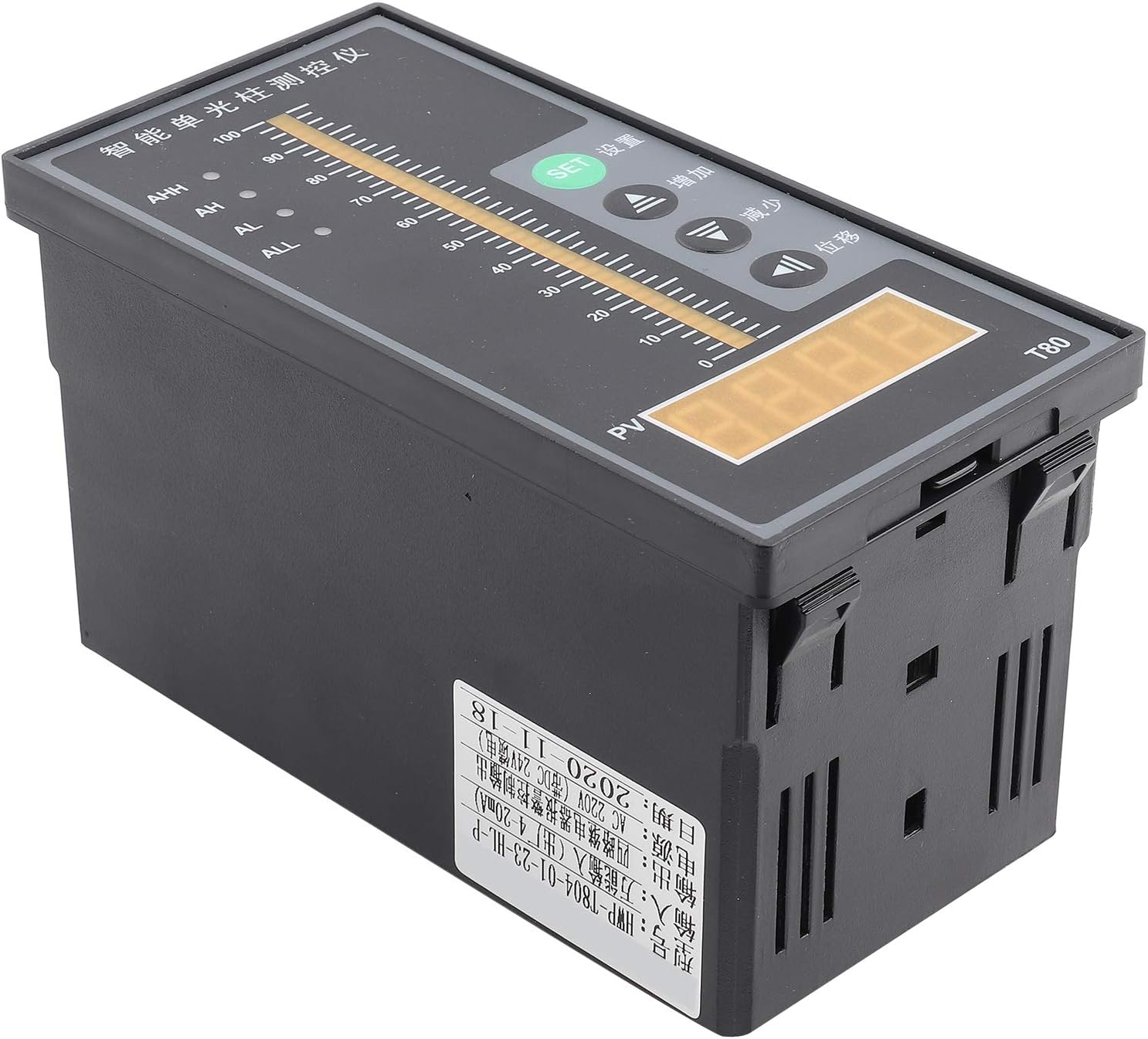
Figure 2.1: Front view of the Walfront T80 Liquid Level Display Controller, showing the light column display, digital PV display, and control buttons (SET, Up, Down, Mobile).

Figure 2.2: Detailed view of the T80 display and control panel. It highlights the Ultimate Upper Limit Alarm Switch (AHH), Upper Limit Alarm Switch (AH), Lower Limit Alarm Switch (AL), Ultimate Lower Limit Alarm Switch (ALL) indicators, Measuring Light Column Display, Measuring Display (PV), SET Confirm Button, Up Button, Down Button, and Mobile Button.
3. Setup and Installation
Proper installation is crucial for the accurate and reliable operation of the T80 controller. Follow these steps carefully.
3.1 Wiring Connections
The T80 controller requires careful wiring for power, the liquid level transmitter, and alarm outputs. Refer to the wiring diagrams below.

Figure 3.1: Wiring diagram for the Walfront T80. This diagram illustrates how to connect the liquid level transmitter (red wire to "+", black wire to "-") and the 220V AC power supply. It also shows connections for ultimate lower limit alarm switch, lower limit alarm switch, upper limit alarm switch, and ultimate upper limit alarm switch.

Figure 3.2: Drain wiring diagram for the Walfront T80. This diagram shows connections for a water level probe ("A" and "B" for the probe, with "B" being the level probe "-"). It also indicates that "C" and "D" connect to a pump and electromagnetic valve (>3A) for cooperation with the contactor or for upper limit alarm. "E" and "F" connect to the 220V power supply.
3.2 Power Supply
- The T80 controller operates on an AC 220V input voltage.
- Ensure the power supply is stable and within the specified voltage range.
- Connect the 220V power supply to the designated terminals as shown in Figure 3.1 and 3.2 (terminals 23 and 24, or E and F).
3.3 Transmitter Connection
- Connect the liquid level transmitter's red wire to the "+" terminal and the black wire to the "-" terminal on the T80 controller (refer to Figure 3.1).
- The transmitter provides a 4-20mA output signal.
3.4 Alarm Output Connections
- The T80 provides outputs for ultimate upper limit (AHH), upper limit (AH), lower limit (AL), and ultimate lower limit (ALL) alarms.
- Connect external devices such as pumps or electromagnetic valves to terminals C and D for control based on alarm conditions, ensuring the current does not exceed 3A.
4. Operating Instructions
This section details how to operate the Walfront T80 controller and interpret its display.
4.1 Display Elements
- Measuring Light Column Display: A vertical bar graph indicating the current liquid level from 0 to 100%.
- Measuring Display (PV): A digital display showing the precise liquid level value.
- Alarm Indicators:
- AHH: Ultimate Upper Limit Alarm.
- AH: Upper Limit Alarm.
- AL: Lower Limit Alarm.
- ALL: Ultimate Lower Limit Alarm.
4.2 Control Buttons
- SET Button: Used to enter parameter setting mode and confirm selections.
- Up Button (▲): Used to increase values or navigate through menu options.
- Down Button (▼): Used to decrease values or navigate through menu options.
- Mobile Button (◀): Used to shift the cursor or select digits during parameter setting.
4.3 Parameter Setting (General Procedure)
- Press the SET button to enter the parameter setting mode. The display will show a parameter code.
- Use the Up or Down buttons to navigate through different parameters (e.g., alarm thresholds, calibration settings).
- Once the desired parameter is selected, press SET again to view its current value.
- Use the Up, Down, and Mobile buttons to adjust the value.
- Press SET to confirm the new value and save it.
- To exit the setting mode, press and hold SET for a few seconds, or wait for a timeout.
4.4 Example of Operation: Liquid Level Measurement
The T80 continuously monitors the liquid level and displays it on both the light column and digital PV display. When the liquid level changes, the display updates in real-time.

Figure 4.1: Example of liquid level measurement using the Walfront T80. The image shows a pump starting to fill water into a tank, with the T80 displaying the rising liquid level and an AC contactor closing to control the pump.
5. Maintenance
Regular maintenance ensures the longevity and accuracy of your Walfront T80 controller.
- Cleaning: Keep the display panel and housing clean using a soft, dry cloth. Avoid abrasive cleaners or solvents.
- Inspection: Periodically check all wiring connections for tightness and signs of corrosion or damage.
- Sensor Maintenance: The liquid level sensor probe should be inspected for any buildup or fouling depending on the measured medium. Clean the probe as necessary, following guidelines for the specific sensor type.
- Environmental Conditions: Ensure the controller is operated within its specified environmental conditions (temperature, humidity) to prevent damage.
6. Troubleshooting
This section provides solutions to common issues you might encounter with the T80 controller.
| Problem | Possible Cause | Solution |
|---|---|---|
| No display/Power off | No power supply; incorrect wiring; blown fuse. | Check 220V AC power connection. Verify wiring according to Figure 3.1. Check internal fuse if accessible (consult qualified personnel). |
| Inaccurate liquid level reading | Sensor fouling; incorrect calibration; damaged sensor/transmitter. | Clean the sensor probe. Recalibrate the device if calibration parameters are accessible. Inspect sensor and transmitter wiring. Replace if damaged. |
| Alarm not triggering or triggering incorrectly | Incorrect alarm threshold settings; wiring issue with alarm output. | Verify alarm threshold settings (AHH, AH, AL, ALL) in parameter mode. Check wiring to external alarm devices (C and D terminals). |
| Buttons unresponsive | Temporary software glitch; physical button damage. | Power cycle the device (turn off and on). If issue persists, contact support. |
7. Specifications
Detailed technical specifications for the Walfront T80 Liquid Level Display Controller.
| Parameter | Value |
|---|---|
| Model | T80 |
| Input Voltage | AC 220V |
| Output Signal | 4-20mA (from transmitter) |
| Measuring Medium | Liquid (water, oil, wastewater) |
| Material | Stainless Steel (probe), other materials for housing |
| Operating Mode | Automatic |
| Current Rating | 20 mA (output) |
| Contact Type | Normally Open (for alarm outputs) |
| Connector Type | Screw Terminals |
| Mounting Type | Flange Mount |
| Product Dimensions (L x W x H) | 20 x 20 x 12 cm |
| Product Weight | 380 grams |
8. Warranty and Support
For warranty information or technical support, please contact Walfront customer service. Keep your purchase receipt as proof of purchase.
- Manufacturer: Walfront
- Contact: Refer to the seller's information on the purchase platform or the official Walfront website for support channels.
- Spare Parts: Information regarding spare parts availability is not provided.


