1. Introduction
Thank you for choosing the Aexit ST-M15-2 Float Switch Liquid Level Controller. This device is designed for reliable and accurate sensing and regulation of liquid levels in various applications, including water tanks, barrels, sinks, and wells. It provides signals when the liquid level reaches predefined upper or lower switching values, enabling automated control of water supply or drainage systems.
Please read this manual thoroughly before installation and operation to ensure safe and efficient use of the product.
2. Package Contents
- 1 x Aexit ST-M15-2 Float Switch Liquid Level Controller (with 2m/6.6Ft cable)
3. Specifications
| Product Name | Float Switch Liquid Level Controller |
| Model | ST-M15-2 |
| Use For | Water Service, Water Draining |
| Microswitch | AC 250V 10(8)A ~380V 10(4)A |
| Max. Work Temperature | 70ºC |
| Working Life | >=50000 cycles |
| Max. Working Pressure | 1 Bar |
| Circuit Break Capacity | 250V 1KW |
| Contacts | NO+NC (Normally Open + Normally Closed) |
| Cable Length | 2m / 6.6Ft |
| Floater Size (L*W*H) | 103 x 78 x 44mm / 4" x 3" x 0.17" |
| Thread Diameter | 18mm / 0.71" |
| Cylinder Size (L*D) | 59 x 49mm / 2.4" x 2" |
| Material | PVC, Electric Parts |
| Color | Yellow, Black, Blue |
| Net Weight | 447g |
| Total Weight | 476g |
| Voltage | 220 Volts |
| Power Source | Corded Electric |
| Sensor Technology | Contact Sensor |
4. Safety Information
Please observe the following safety precautions to prevent injury or damage to the product:
- Do not allow children to have casual contact with the device.
- Handle with care; do not shake forcefully.
- Avoid use in extreme temperatures such as open flames and super high temperatures.
- Ensure proper electrical connections are made by a qualified professional.
- Always disconnect power before installation, maintenance, or troubleshooting.
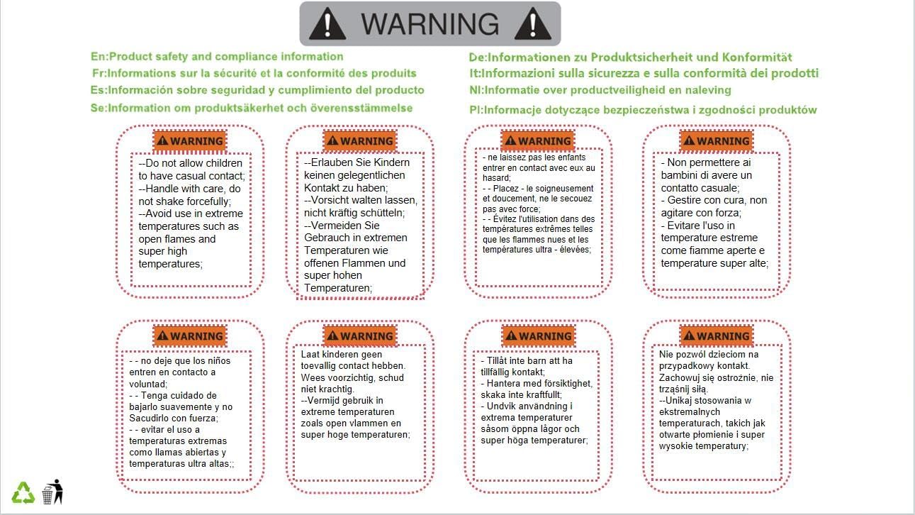
Figure 4.1: Multi-language safety warning label.

Figure 4.2: Product packaging showing safety information.
5. Setup and Installation
The float switch is designed for simple installation. It typically hangs vertically within the liquid, with the counterweight used to set the desired switching level.
5.1 Component Overview

Figure 5.1: Float Switch with cable and counterweight. This image shows the main components of the float switch, including the yellow and blue float body, the black cable, and the cylindrical black counterweight.

Figure 5.2: Float Switch with full cable length. This image provides a broader view of the float switch, illustrating the length of the cable and how the counterweight is positioned along it.
5.2 Wiring Instructions
The float switch features three wires for connection to your control system. The black wire is the common line. The other two wires (blue and brown) are used depending on whether the system is for water supply or drainage.
- Water Supply System: Connect the black wire (common) and the blue wire. This configuration typically means the pump will turn on when the water level drops and turn off when it rises to the desired level.
- Water Drainage System: Connect the black wire (common) and the brown wire. This configuration typically means the pump will turn on when the water level rises and turn off when it drops to the desired level.
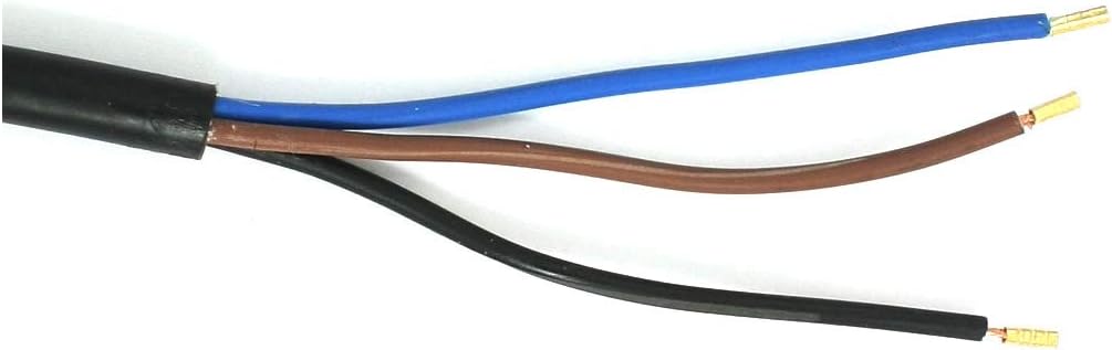
Figure 5.3: Cable wiring detail. This image shows a close-up of the three colored wires (black, blue, brown) at the end of the float switch cable, ready for electrical connection.
Important: All electrical connections should be performed by a qualified electrician in accordance with local electrical codes and regulations. Ensure the power supply is disconnected before making any connections.
5.3 Setting the Switching Level
The switching level is determined by the position of the black cylindrical counterweight on the cable. By adjusting the counterweight's position, you can set the range of liquid level fluctuation that triggers the switch. The float will pivot around the counterweight, activating the internal microswitch when it reaches a certain angle.
6. Operation
Once installed and wired correctly, the Aexit ST-M15-2 Float Switch operates automatically. As the liquid level changes, the float body will move up or down. When the float reaches the pre-set activation point (determined by the counterweight and the pivot of the float), the internal microswitch will change its contact state (NO to NC or NC to NO), sending a signal to the connected control system (e.g., a pump controller).
The switch is designed for continuous operation within its specified temperature and pressure limits.
7. Maintenance
The Aexit ST-M15-2 Float Switch is designed for low maintenance. However, periodic checks are recommended to ensure optimal performance:
- Cleaning: Periodically inspect the float body and cable for any buildup of debris, algae, or scale that might impede its free movement. Clean with mild soap and water if necessary.
- Cable Inspection: Check the cable for any signs of wear, cracks, or damage, especially where it enters the float body or where it is secured.
- Counterweight Position: Verify that the counterweight remains securely in its desired position and has not shifted, which could alter the switching level.
- Functionality Test: If possible and safe to do so, periodically test the switch by manually raising or lowering the liquid level to confirm it activates at the expected points.
Always disconnect power to the device before performing any maintenance.
8. Troubleshooting
If you experience issues with your float switch, consider the following common problems and solutions:
- Switch Not Activating:
- Check electrical connections: Ensure all wires are securely connected according to the wiring diagram (black-blue for supply, black-brown for drainage).
- Verify power supply: Confirm that power is reaching the control circuit connected to the float switch.
- Inspect for obstructions: Make sure the float body can move freely and is not obstructed by tank walls, pipes, or debris.
- Adjust counterweight: The counterweight might be set too high or too low, preventing the float from reaching the activation angle.
- Erratic Operation / False Triggers:
- Check for turbulence: Excessive turbulence in the liquid can cause the float to bob erratically. Consider installing a stilling tube around the float if this is an issue.
- Inspect for damage: Physical damage to the float body or cable could affect its buoyancy or internal mechanism.
- Verify wiring integrity: Loose or corroded connections can lead to intermittent signals.
- Switch Always On/Off:
- Check float position: Ensure the float is not stuck in an extreme up or down position.
- Internal switch failure: If all external factors are ruled out, the internal microswitch may have failed. The unit may need replacement.
If troubleshooting steps do not resolve the issue, contact customer support.
9. Warranty and Support
Aexit products are manufactured to high-quality standards. For warranty information or technical support, please refer to the contact details provided with your purchase or visit the official Aexit website. Please have your product model number (ST-M15-2) and purchase details ready when contacting support.


