1. Introduction
This manual provides essential instructions for the safe and efficient operation of the Hilitand AT1-0750X Variable Frequency Drive (VFD). This device is designed to control the speed of three-phase AC motors, commonly used in applications such as pumps and fans. It utilizes advanced PWM control technology for precise speed regulation and features robust electromagnetic compatibility.
1.1 Key Features
- PWM Control Technology: Optimizes control and electromagnetic compatibility, reducing noise and interference.
- Unique Control Method: Achieves high torque, high precision, and a wide speed regulation range.
- Robust Performance: Good anti-drop performance and adaptability to sudden power interference, temperature, humidity, and dust.
- Simple Operation: Easy to use with quick response for starting and stopping, and significant torque at low speeds.
- Intelligent Protection: Features intelligent protection against overcurrent, overvoltage, overheating, overload, and undervoltage.
1.2 Safety Warnings
Failure to follow these safety instructions may result in death, serious injury, or property damage.
- Always read the entire instruction manual before operating the VFD.
- Ensure all wiring is correct and secure. Connecting AC power to the U/V/W output terminals will damage the inverter.
- Do not connect the AC power supply to the output terminals (U, V, W).
- Ensure the VFD is properly grounded to prevent electrical shock.
- Do not install or operate the VFD in flammable or explosive environments.
- Only qualified and trained personnel should perform installation, wiring, and maintenance tasks.
- Do not open the VFD cover when power is applied. High voltage is present inside, even after power-off, due to capacitor discharge. Wait for the charge indicator to extinguish.
2. Setup and Installation
2.1 Unpacking and Inspection
Carefully unpack the VFD and inspect it for any signs of damage during transit. Verify that all components are present according to the packing list. If any damage or missing parts are found, contact your supplier immediately.
2.2 Mounting
Mount the VFD in a vertical position on a stable, non-flammable surface. Ensure adequate clearance around the unit for proper ventilation and heat dissipation. The VFD is designed with a heatsink for efficient cooling.

Avoid locations with excessive dust, high humidity, direct sunlight, or corrosive gases. The operating temperature range should be maintained as specified in the technical data.
2.3 Wiring
All wiring must be performed by a qualified electrician in accordance with local and national electrical codes. Ensure power is disconnected before making any connections.

- Power Input (L, N): Connect the single-phase 220V AC power supply to the 'L' and 'N' terminals.
- Motor Output (U, V, W): Connect the three-phase motor to the 'U', 'V', and 'W' terminals. Ensure correct phase sequence for desired motor rotation.
- Grounding: Connect the ground terminal (marked with ⚧) to a reliable earth ground. This is crucial for safety.

3. Operating Instructions
3.1 Control Panel Overview
The VFD features an intuitive control panel for easy operation and parameter adjustment.
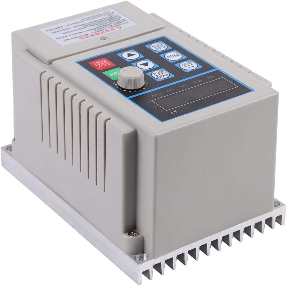
- RUN Button (Green): Initiates motor operation.
- STOP/RESET Button (Red): Stops motor operation and resets any fault conditions.
- FWD/REV Buttons: Changes the direction of motor rotation (Forward/Reverse).
- DISP Button: Toggles between different display modes (e.g., frequency, current, voltage).
- PROG Button: Enters or exits the parameter programming mode.
- FUNC/DATA Button: Used to select parameters or confirm data entry.
- Up/Down Arrows: Navigates through parameters or adjusts values.
- Rotary Knob: Provides fine adjustment for frequency/speed in manual mode.
- Digital Display: Shows operating status, frequency, and parameter values.
3.2 Basic Operation
- Power On: After ensuring all wiring is correct and secure, apply 220V AC power to the VFD. The digital display will illuminate.
- Start Motor: Press the RUN button. The motor will start and accelerate to the set frequency.
- Adjust Speed: Use the rotary knob or the Up/Down arrow buttons to adjust the output frequency, thereby changing the motor speed. The display will show the current operating frequency.
- Change Direction: Press the FWD or REV button to change the motor's rotation direction. Ensure the motor is stopped or at a very low speed before changing direction to prevent mechanical stress.
- Stop Motor: Press the STOP/RESET button. The motor will decelerate and stop.
3.3 Parameter Settings
The VFD allows for customization of various operating parameters to suit specific application requirements. Refer to the detailed parameter list (usually provided in a separate, comprehensive manual) for specific codes and functions.
- Press the PROG button to enter parameter programming mode.
- Use the Up/Down arrow buttons to navigate through parameter groups or individual parameters.
- Press FUNC/DATA to select a parameter or enter its editing mode.
- Use the Up/Down arrows or rotary knob to adjust the parameter value.
- Press FUNC/DATA again to save the new value.
- Press PROG to exit programming mode.
4. Maintenance
Regular maintenance ensures the longevity and reliable operation of your VFD.
- Cleaning: Periodically clean the VFD's exterior, especially the heatsink fins, to ensure proper heat dissipation. Use a soft, dry cloth. Do not use liquid cleaners.
- Connection Checks: Regularly inspect all wiring connections for tightness and signs of corrosion. Loose connections can lead to poor performance or damage.
- Environmental Conditions: Ensure the operating environment remains within specified temperature, humidity, and dust levels. Excessive dust or moisture can lead to internal damage.
- Ventilation: Confirm that ventilation openings are not obstructed.
5. Troubleshooting
This section provides solutions to common issues. For complex problems, contact technical support.
| Problem | Possible Cause | Solution |
|---|---|---|
| VFD does not power on | No input power; Blown fuse; Internal fault | Check power supply; Check fuses; Contact support if power is present and fuses are good. |
| Motor does not run | Incorrect wiring; Motor fault; VFD in STOP mode; Fault code displayed | Verify motor and VFD wiring; Check motor condition; Press RUN button; Check display for fault codes and refer to parameter manual. |
| Motor speed is incorrect | Frequency setting incorrect; Parameter misconfiguration | Adjust frequency using rotary knob/arrows; Check relevant speed control parameters (e.g., max frequency, min frequency). |
| VFD displays an error code | Overcurrent, overvoltage, overheating, overload, undervoltage, etc. | Note the error code. Refer to the comprehensive parameter manual for specific error definitions and troubleshooting steps. Address the underlying cause (e.g., reduce load, check ventilation). Press STOP/RESET to clear. |
6. Specifications
Technical specifications for the Hilitand AT1-0750X Variable Frequency Drive.
| Specification | Value |
|---|---|
| Manufacturer | Hilitand |
| Model Name | AT1-0750X (Internal Reference: Hilitandk6aftgnzyp) |
| Input Voltage | 220 Volts (AC) |
| Output Voltage | 220 Volts |
| Power Rating | 0.75 kW |
| Product Dimensions (L x W x H) | 12 x 17 x 15 cm (approximately 4.7 x 6.7 x 5.9 inches) |
| Item Weight | 1.03 Kilograms (approximately 2.27 pounds) |
| Material | Plastic |
| Recommended Uses | Workshop / Construction Site |
| UPC | 794419667717 |
7. Warranty and Support
For warranty information, technical support, or service inquiries, please refer to the documentation provided with your purchase or contact the Hilitand customer service department. Keep your purchase receipt as proof of purchase.


