1. Introduction
This manual provides essential information and instructions for the Walfront ESP32-D0WDQ6 WiFi Bluetooth Camera Module Development Board. The WROOM-32 is a versatile Wi-Fi, Bluetooth, and BLE MCU module designed for a wide range of applications, from low-power sensor networks to demanding tasks like audio coding and MP3 decoding.
Key Features:
- Integrated ESP32-D0WDQ6 chip, offering extendable and adaptive capabilities.
- Dual CPU cores with individual control and power management.
- Adjustable clock frequency from 80 MHz to 240 MHz.
- Low-power coprocessor for continuous monitoring of peripherals and analog thresholds.
- Rich integrated peripherals including capacitive touch sensors, Hall sensors, low-noise sensor amplifier, SD card interface, Ethernet interface, high-speed SDIO, UART, I2S, and I2C.
- Stable USB to TTL chips for reliable serial communication.
- Supports automatic download, eliminating the need for manual switching between download and run modes.
- Compatible with development environments like (Cygwin and msys32 simulation environment) and system.
2. What's in the Box
- 1 x Walfront ESP32-D0WDQ6 WiFi Bluetooth Camera Module Development Board
3. Specifications
| Feature | Detail |
|---|---|
| Processor | Dual-core 32-bit LX6 MCU (ESP32-D0WDQ6) |
| RAM | DDR3L |
| Wireless Type | Bluetooth, Wi-Fi |
| Operating System Support | Linux, Windows |
| Item Weight | 0.352 ounces (approx. 10g) |
| Product Dimensions | 3.15 x 2.76 x 2.36 inches (approx. 50 x 28 mm) |
| Included Components | 1 * ESP32 Module |
 Image: Dimensions of the Walfront ESP32-D0WDQ6 module.
4. Setup and Assembly
4.1. Overview of the Module
The Walfront ESP32-D0WDQ6 development board features the ESP32-WROOM-32 module, a USB-C port for power and data, and pin headers for external connections. It includes an onboard antenna for Wi-Fi and Bluetooth connectivity.
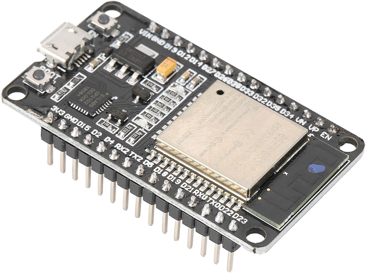 Image: Walfront ESP32-D0WDQ6 Development Board.
 Image: Front and back views of the ESP32-D0WDQ6 module.
 Image: Close-up of the ESP32-WROOM-32 chip.
4.2. Pin Soldering (If required)
If your module did not come with pre-soldered pin headers, you will need to solder them to the board. This process involves carefully attaching the header pins to the designated pads on the development board using a soldering iron and solder wire. Ensure proper ventilation and safety precautions during soldering.
Video: Demonstration of soldering pin headers to the ESP32 development board.
4.3. Prototype Circuit Assembly
To begin prototyping, insert the ESP32 module into a breadboard. Ensure all pins are correctly aligned and firmly seated. This allows for easy connection of external components without permanent soldering.
Video: Illustrates inserting the ESP32 module into a breadboard for circuit assembly.
4.4. Hardware Connection Example (LED)
This section provides an example of connecting an LED to the ESP32 module. Refer to the diagram and video for proper wiring. Ensure power and data lines are connected to the correct pins on both the ESP32 and the LED.
 Image: Wiring diagram for connecting an OLED display to the ESP32 module.
Video: Demonstrates connecting external hardware, specifically an LED, to the ESP32 module on a breadboard.
5. Operating Instructions
5.1. Firmware Flashing
To program the ESP32 module, you will need to flash firmware onto it. This typically involves connecting the module to your computer via the USB-C port and using a compatible Integrated Development Environment (IDE) such as MicroPython or Arduino IDE. The module supports automatic download, simplifying the flashing process.
Video: Shows the process of flashing firmware (MicroPython code) to the ESP32 module using a computer.
5.2. Basic Operation Demonstration
After successful firmware flashing, the module can execute programmed tasks. The video demonstrates a simple LED blinking program, illustrating basic output control. Observe the connected LED for expected behavior.
Video: A demonstration of the ESP32 module controlling an external LED to blink, indicating successful program execution.
6. Troubleshooting
- Module not recognized by computer: Ensure the USB-C cable is fully inserted and functional. Verify that the necessary USB drivers (e.g., CP210x drivers for the onboard USB-to-UART bridge) are installed on your computer.
- Firmware upload failure: Check your IDE settings for the correct COM port and board selection. Ensure the module is in programming mode (if manual mode is required, though this module supports automatic download).
- External components not working: Double-check all wiring connections against your circuit diagram. Verify power supply to external components and ensure correct pin assignments in your code.
- Wi-Fi/Bluetooth connectivity issues: Ensure your antenna is properly connected (if external) or that the onboard antenna is not obstructed. Verify network credentials and configurations in your code.
7. Maintenance
- Cleaning: Keep the module clean and free from dust and debris. Use a soft, dry brush or compressed air for cleaning. Avoid liquid cleaners.
- Storage: Store the module in an anti-static bag in a cool, dry place when not in use to prevent electrostatic discharge and moisture damage.
- Handling: Handle the module by its edges to avoid touching sensitive components and pins.
8. Warranty and Support
For warranty information and technical support, please refer to the Walfront official website or contact your retailer. Keep your purchase receipt for warranty claims.
Manufacturer: Walfront
Date First Available: November 28, 2018


