1. Introduction
This manual provides essential information for the installation, operation, and maintenance of the WAGO 750-467 I/O System 2 Channel Analog 0-10V-DC Input Module. The WAGO 750-467 is designed for industrial automation applications, enabling the acquisition of analog voltage signals within a 0-10V DC range. It is a critical component for integrating analog sensors and devices into a digital control system.
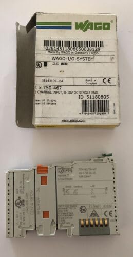
Figure 1: The WAGO 750-467 I/O System 2 Channel Analog 0-10V-DC Input Module. The image displays the module both within its original WAGO packaging, showing product details like model number and input specifications, and as a standalone unit, highlighting its compact design and connection points.
2. Setup and Installation
Proper installation is crucial for the reliable operation of the WAGO 750-467 module. Follow these guidelines:
- Safety First: Ensure all power to the I/O system and connected devices is disconnected before installation. Observe all local and national electrical codes.
- Mounting: The module is designed for DIN-rail mounting. Snap the module onto the DIN rail securely within the I/O node assembly.
- Wiring:
- Connect the 0-10V DC analog input signals to the designated terminals on the module. Refer to the module's terminal diagram for correct pin assignments.
- Ensure proper grounding and shielding of analog signal cables to minimize noise interference.
- Use appropriate wire gauges for all connections to prevent voltage drop and ensure secure connections.
- Power Connection: Verify that the I/O node's power supply is correctly connected and provides the necessary voltage for the system.
- Configuration: Depending on the specific I/O controller or PLC used, the module may require software configuration to define input ranges, scaling, and data types. Consult your controller's programming manual for details.
3. Operating Instructions
The WAGO 750-467 module functions as a 2-channel analog input for 0-10V DC signals. Once properly installed and configured, it will convert the incoming analog voltage signals into digital values that can be processed by the connected I/O controller or PLC.
- Signal Acquisition: The module continuously monitors the voltage at its input channels.
- Data Conversion: The analog voltage is converted into a digital representation, typically a 16-bit value, which is then made available to the fieldbus coupler or controller.
- Data Access: The digital input values can be read by the PLC program for control logic, monitoring, or data logging. Refer to your controller's documentation for accessing I/O data.
- LED Indicators: The module may feature status LEDs (e.g., for power, input status) to provide visual feedback on its operational state. Consult the module's technical data sheet for specific LED functions.
4. Maintenance
The WAGO 750-467 module is designed for long-term, maintenance-free operation in industrial environments. However, periodic checks can help ensure continued reliability:
- Visual Inspection: Periodically inspect the module and its connections for any signs of physical damage, loose wiring, or corrosion.
- Environmental Conditions: Ensure the operating environment remains within the specified temperature and humidity ranges to prevent premature component failure.
- Cleaning: If necessary, gently clean the module's exterior with a soft, dry cloth. Do not use abrasive cleaners or solvents. Ensure power is off before cleaning.
- Firmware Updates: While rare for I/O modules, check the WAGO website for any recommended firmware updates for your specific module and controller combination.
5. Troubleshooting
If you encounter issues with the WAGO 750-467 module, consider the following troubleshooting steps:
| Problem | Possible Cause | Solution |
|---|---|---|
| Module LED is off | No power to the I/O node or module; incorrect mounting. | Check power supply to the I/O node. Ensure the module is correctly seated on the DIN rail and connected to the bus coupler. |
| Incorrect analog readings | Incorrect wiring; sensor malfunction; incorrect scaling in PLC program; electrical noise. | Verify wiring against the terminal diagram. Test the analog sensor. Check PLC program for correct scaling and input range settings. Ensure proper shielding of signal cables. |
| Module not recognized by PLC | Incorrect configuration in PLC software; faulty module or bus coupler. | Verify the module type and address are correctly configured in the PLC programming software. Check the bus coupler's status. Try reseating the module. |
If these steps do not resolve the issue, contact WAGO technical support.
6. Specifications
Key technical specifications for the WAGO 750-467 I/O System 2 Channel Analog 0-10V-DC Input Module:
- Model Number: 750-467
- Module Type: Analog Input Module
- Number of Channels: 2
- Input Voltage Range: 0 - 10 V-DC
- Manufacturer: WAGO
- Product Dimensions: 5 x 4 x 1 inches (approximately)
- Weight: 1 Pound (approximately)
- First Available Date: November 22, 2018
- ASIN: B07KSHTQ7R
7. Warranty and Support
For detailed warranty information, please refer to the official WAGO warranty policy available on their website or included with your purchase documentation. WAGO provides comprehensive technical support for its products.
WAGO Official Website: www.wago.com
For technical assistance, product documentation, or service inquiries, please visit the support section of the WAGO website or contact their customer service directly.


