1. Introduction
This manual provides detailed instructions for the safe and efficient use of your DROK DC-DC Buck Converter. This module is designed to step down a higher DC input voltage to a lower, adjustable DC output voltage, featuring an LCD display for real-time monitoring of voltage, current, and power.
2. Product Features
- Wide Input Voltage Range: DC 6.5V to 36V.
- Adjustable Output Voltage: DC 1.2V to 32V. Factory default output is 5V.
- High Output Current: Stable operation at 3.5A for extended periods, capable of reaching 4.5A with adequate heat dissipation. Adjustable current limit is approximately 4.2A-4.5A.
- LCD Display: Shows input voltage, output voltage, output current, and output power.
- High Display Resolution: Voltage resolution of 0.05V, current resolution of 0.005A.
- Display Accuracy: Voltage display accuracy of ±0.1V, current display accuracy of ±0.05A.
- Button Control: Easy adjustment of output voltage and control of output ON/OFF state without a screwdriver.
- Input Reverse Connection Protection: Protects the module from damage due to incorrect input polarity.
- Protective Casing: Includes a transparent acrylic case to prevent physical damage to the module.
3. Safety Precautions
- Ensure correct input voltage polarity. The module has input reverse connection protection, but always verify connections.
- There is no reverse current protection on the output terminals. Do not connect a battery or other power source to the output without an external diode to prevent reverse current flow, as this can damage the module.
- Do not short-circuit the Input IN- terminal to the Output OUT- terminal. This will disable the constant current function.
- Ensure proper ventilation, especially when operating at higher currents (above 3.5A) to allow for adequate heat dissipation.
- Always verify the output voltage setting before connecting any load to prevent damage to your devices.
- Handle the module with care, especially during assembly of the acrylic case, to avoid damage to components.
4. Specifications
| Parameter | Value |
|---|---|
| Input Voltage Range | DC 6.5V - 36V |
| Output Voltage Range | DC 1.2V - 32V (Adjustable) |
| Output Current (Stable) | 3.5A |
| Output Current (Max with Heat Dissipation) | 4.5A |
| Output Power | 75W |
| Voltage Display Resolution | 0.05V |
| Current Display Resolution | 0.005A |
| Voltage Display Accuracy | ±0.1V |
| Current Display Accuracy | ±0.05A |
| Dimensions | 14.7 x 8 x 5.2 cm |
| Weight | 70 g |
5. Setup
5.1 Component Identification
Familiarize yourself with the components of the buck converter module:

Figure 1: Component layout of the DROK buck converter. Labels indicate input/output terminals, LCD display, control buttons, and the voltage adjustment potentiometer.
5.2 Acrylic Case Assembly
The module comes with a transparent acrylic case for protection. Assembly is straightforward:
- Identify the top and bottom acrylic plates, standoffs, and screws.
- Carefully align the bottom acrylic plate with the mounting holes on the PCB.
- Insert the brass standoffs through the bottom plate and into the PCB.
- Place the top acrylic plate over the standoffs, ensuring all cutouts align with the module's components (terminals, buttons, screen).
- Secure the top plate with the remaining screws. Do not overtighten.
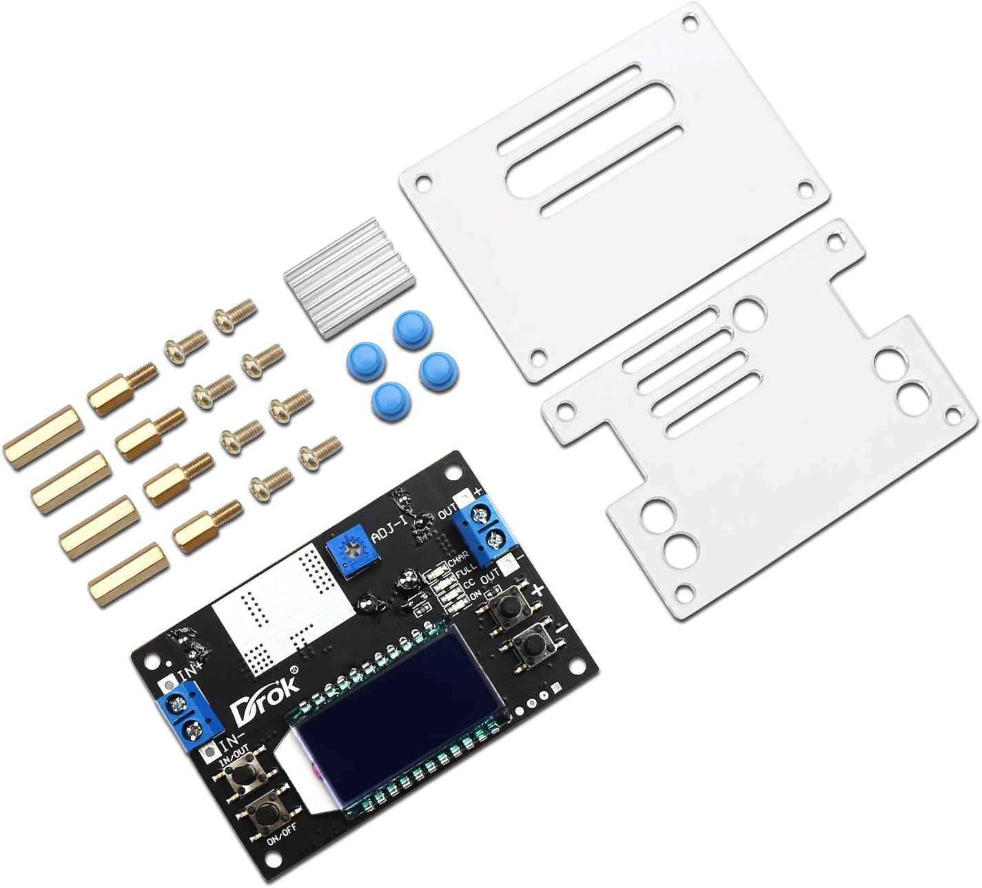
Figure 2: Disassembled module with acrylic case components.

Figure 3: Assembled module with protective case.
5.3 Wiring Connections
Connect your power source and load to the module using the screw terminals:
- Input (IN+ / IN-): Connect your DC power source (6.5V-36V) to these terminals. Ensure correct polarity: IN+ for positive, IN- for negative.
- Output (OUT+ / OUT-): Connect your load to these terminals. Ensure correct polarity: OUT+ for positive, OUT- for negative.
Note: Always double-check wiring before applying power.
6. Operating Instructions
6.1 Power On/Off
- After connecting the input power, the LCD will light up.
- Press the ON/OFF button (usually on the left side) to toggle the output power.
- To set the default power-on state (output ON or OFF), press and hold the ON/OFF button. The module will remember this setting for subsequent power cycles.
6.2 Adjusting Output Voltage
The output voltage is adjusted using the two buttons on the right side of the module:
- Press the '+' button to increase the output voltage.
- Press the '-' button to decrease the output voltage.
- The LCD will display the current output voltage during adjustment.
6.3 LCD Display Modes
The module features an LCD that can display various parameters. Use the button on the left (often labeled 'IN/OUT' or similar) to cycle through display modes:
- Output Voltage (OUT V): Displays the current output voltage.
- Input Voltage (IN V): Displays the current input voltage.
- Input/Output Voltage (IN/OUT V): Alternates between input and output voltage display.
- Output Current (OUT A): Displays the current flowing through the output.
- Output Power (OUT W): Displays the calculated output power.
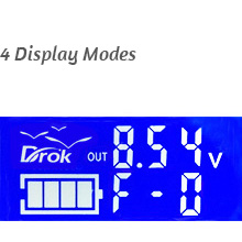
Figure 4: Output Voltage Display
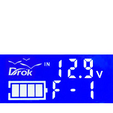
Figure 5: Input Voltage Display
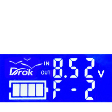
Figure 6: Input/Output Voltage Display

Figure 7: USB Output Voltage Display (if applicable)
6.4 Constant Current (CC) Adjustment
The module supports constant current output. The current limit can be adjusted using the small potentiometer (ADJ-I) on the board. Turn clockwise to increase the current limit. This is typically set to approximately 4.2A-4.5A at the factory.
7. Maintenance
- Keep the module clean and free from dust and debris. Use a soft, dry cloth for cleaning.
- Ensure adequate airflow around the module, especially when operating at higher loads, to prevent overheating.
- Regularly check wiring connections for tightness and signs of wear or corrosion.
- Avoid exposing the module to moisture, extreme temperatures, or corrosive environments.
8. Troubleshooting
| Problem | Possible Cause | Solution |
|---|---|---|
| No display/No output | No input power; Incorrect input polarity; Output turned off. | Check input power connections; Verify input polarity; Press the ON/OFF button to enable output. |
| Output voltage cannot be adjusted | Potentiometer at its limit; Faulty potentiometer. | Ensure the adjustment buttons are being pressed correctly; If still unresponsive, contact support. |
| Constant current function not working | Input IN- short-circuited to Output OUT-. | Check wiring to ensure IN- and OUT- are not connected. |
| Module overheating | Excessive load current; Insufficient ventilation. | Reduce load current; Ensure adequate airflow around the module; Consider adding a fan for continuous high-current operation. |
9. Product Videos
Watch these official videos for additional guidance on using your DROK Buck Converter:
Video 1: Demonstration of the buck converter's features and operation.
Video 2: Detailed guide on setting up and adjusting the output voltage.
Video 3: Short overview of the module's display functions.
Video 4: Comprehensive tutorial on advanced usage and applications.
10. Warranty and Support
For warranty information or technical support, please refer to the product packaging or contact your retailer. Keep your purchase receipt for warranty claims.