1. Introduction
This manual provides detailed instructions for the Walfront 3.2 inch 240x320 LCD Display Module. This module features a 65K color display, a 4-wire SPI interface, and an optional touch function. It also includes an integrated SD card slot for expanded functionality. The display is driven by the ILI9341 chip, offering a resolution of 320x240 pixels.
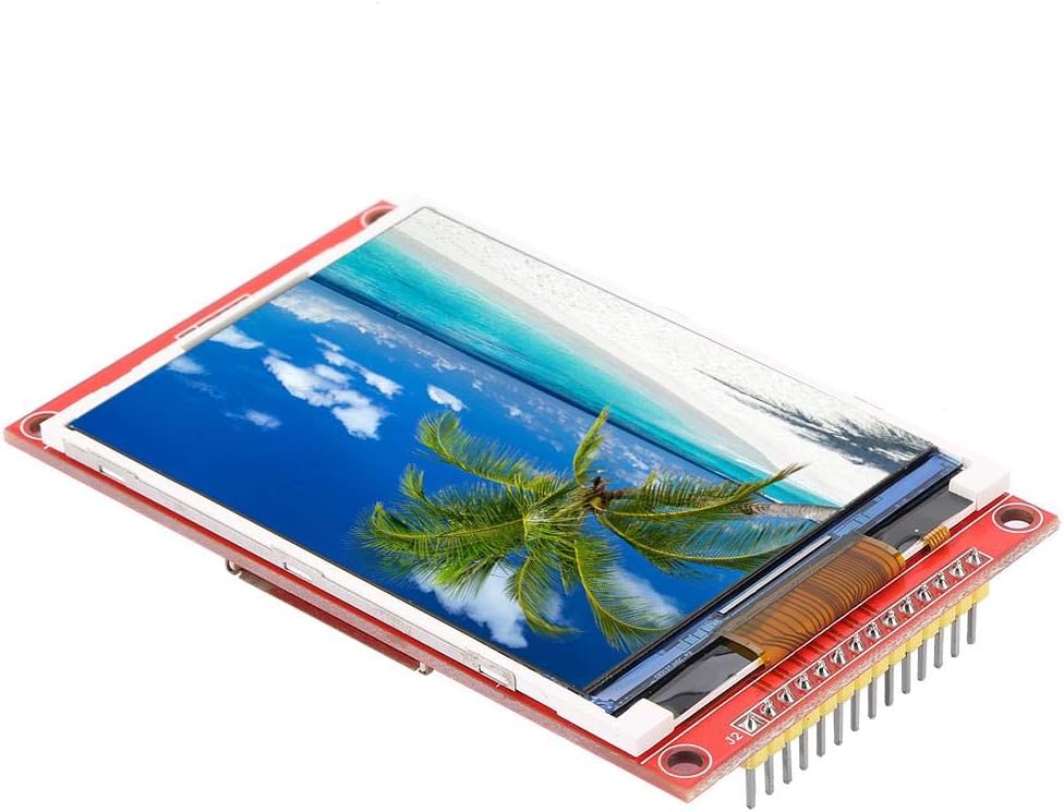
Image 1.1: Walfront 3.2 inch 240x320 LCD Display Module. This image shows the display module from an angled perspective, highlighting its compact size and the vibrant display of a beach scene.
2. Specifications
| Feature | Description |
|---|---|
| Display Size | 3.2 inches |
| Resolution | 320 x 240 pixels |
| Color Depth | 65K colors |
| Driver Chip | ILI9341 |
| Interface | 4-wire SPI |
| Effective Display Area | 48.6 x 64.8 mm |
| Module PCB Plate Size | 55.04 x 89.3 mm |
| VCC Power Supply Voltage | 3.3V ~ 5V |
| Logical IO Port Voltage | 3.3V (TTL) |
| Power Consumption | Approx. 90mA |
| Weight | Approx. 42g / 1.5oz |
| Additional Features | Optional Touch Function, SD Card Slot |
3. Key Features
- Vibrant Display: Features a 3.2-inch color screen capable of displaying 65,000 colors for clear and vivid visuals.
- High Resolution: Offers a 320x240 pixel resolution, providing detailed imagery.
- Efficient Interface: Utilizes a 4-wire Serial Peripheral Interface (SPI) bus, minimizing the number of I/O pins required for display control.
- Expandable Storage: Includes an integrated SD card slot, allowing for easy expansion of data storage and experimental capabilities.
- Optional Touch Function: Available with an optional touch panel for interactive applications.
4. Package Contents
The standard package includes:
- 1 x Walfront 3.2 inch LCD Display Module
5. Pinout and Interface Definition
Understanding the pinout is crucial for proper integration and operation of the display module. The following table details each pin's function:
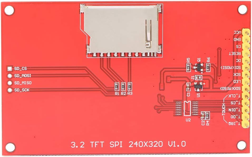
Image 5.1: Rear view of the Walfront 3.2 inch LCD Display Module, showing the pin headers and the SD card slot. The pin labels are visible on the PCB.
| Pin No. | Label | Description |
|---|---|---|
| 1 | VCC | Power input (3.3V ~ 5V) |
| 2 | GND | Power Ground |
| 3 | CS | LCD Chip Select (Active Low) |
| 4 | RESET | LCD Reset (Active Low) |
| 5 | DC | LCD Bus Command/Data Selection (High for Data, Low for Command) |
| 6 | SDI (MOSI) | LCD SPI Data Input (Master Out Slave In) |
| 7 | SCK | LCD SPI Clock Signal |
| 8 | LED | LCD Backlight Control (High level for lighting) |
| 9 | SDO (MISO) | LCD SPI Data Output (Master In Slave Out) |
| 10 | T_CLK | Touch Panel SPI Clock Signal |
| 11 | T_CS | Touch Panel SPI Chip Select (Active Low) |
| 12 | T_DIN | Touch Panel SPI Data Input |
| 13 | T_DO | Touch Panel SPI Data Output |
| 14 | T_IRQ | Touch Panel Interrupt Request Signal |
Note: Pins 10-14 are only relevant for modules equipped with the optional touch function.
6. Setup Instructions
To set up your Walfront 3.2 inch LCD Display Module, follow these general steps:
- Power Connection: Connect the VCC pin to a 3.3V to 5V power supply and the GND pin to the power ground. Ensure stable power delivery.
- SPI Bus Connection: Connect the SCK, SDI (MOSI), and SDO (MISO) pins to the corresponding SPI pins on your microcontroller or development board.
- Control Pins: Connect the CS (Chip Select), RESET, and DC (Data/Command) pins to available digital I/O pins on your microcontroller.
- Backlight Control: Connect the LED pin to an I/O pin or directly to a high logic level (e.g., 3.3V) to enable the backlight.
- Touch Panel (Optional): If your module includes touch functionality, connect T_CLK, T_CS, T_DIN, T_DO, and T_IRQ to appropriate I/O pins on your microcontroller.
- SD Card Slot: If using the SD card slot, ensure your microcontroller's SPI bus can also interface with the SD card, often requiring separate Chip Select lines.
Refer to your microcontroller's documentation and the ILI9341 datasheet for specific wiring diagrams and library usage.

Image 6.1: Front and rear view of the Walfront 3.2 inch LCD Display Module. This image provides a clear perspective of both sides of the module, showing the display on one side and the pin headers and SD card slot on the other, which is helpful for wiring.
7. Operating Instructions
Operating the Walfront LCD Display Module typically involves programming your microcontroller to send commands and data via the SPI interface.
- Initialization: After power-up, the ILI9341 driver chip requires a specific sequence of initialization commands to configure the display. This usually involves setting display modes, gamma correction, and other parameters.
- Displaying Graphics: To display pixels, send pixel data to the display RAM via the SPI bus. Libraries for common microcontrollers (e.g., Arduino, ESP32) often abstract these low-level commands, allowing you to draw shapes, text, and images more easily.
- Touch Input (Optional): If your module has touch functionality, you will need to poll the touch controller (via its own SPI interface) to read touch coordinates. The T_IRQ pin can be used to detect when a touch event occurs.
- SD Card Usage: The integrated SD card slot can be used to store images, fonts, or other data that can be read by your microcontroller and displayed on the screen. Standard SD card libraries can be used for this purpose.
Consult example code and libraries compatible with the ILI9341 driver and your chosen microcontroller for practical implementation.

Image 7.1: Angled view of the Walfront 3.2 inch LCD Display Module, emphasizing the integrated SD card slot on the rear of the PCB. This slot allows for easy expansion of storage for display content.
8. Maintenance
To ensure the longevity and optimal performance of your LCD display module, consider the following maintenance guidelines:
- Handling: Always handle the module by its edges to avoid touching the display surface or damaging components on the PCB.
- Cleaning: Use a soft, lint-free cloth, slightly dampened with distilled water or a specialized screen cleaner, to gently wipe the display surface. Avoid abrasive materials or harsh chemicals.
- Storage: Store the module in a dry, dust-free environment, away from direct sunlight and extreme temperatures.
- Power Supply: Ensure the power supply voltage remains within the specified range (3.3V ~ 5V) to prevent damage to the module.
- Static Discharge: Take precautions against electrostatic discharge (ESD) when handling the module, as electronic components are sensitive to static electricity.
9. Troubleshooting
If you encounter issues with your Walfront LCD Display Module, refer to the following common problems and solutions:
- Display Does Not Power On:
- Verify that both the VCC pin and the LED pin are correctly supplied with power (3.3V-5V). The backlight (LED) requires a high logic level to illuminate.
- Check all power and ground connections for continuity and correct polarity.
- No Display Output / White Screen:
- Ensure the display initialization sequence in your code is correct and matches the ILI9341 driver requirements.
- Confirm that the SPI communication lines (SCK, SDI, SDO) are correctly wired and that data is being transmitted.
- Check the CS, RESET, and DC pins for proper signal levels and timing.
- Incorrect Colors or Distorted Image:
- Review your display driver code for correct color format and pixel data transmission.
- Ensure the display's gamma settings are configured correctly during initialization.
- Touch Function Not Responding (if applicable):
- Verify the connections for the touch panel SPI pins (T_CLK, T_CS, T_DIN, T_DO, T_IRQ).
- Check your code for correct touch controller initialization and polling routines.
- SD Card Not Detected:
- Ensure the SD card is properly inserted and formatted.
- Verify the SD card's SPI connections and its dedicated Chip Select (CS) pin.
- Shared SPI Bus Issues:
- If sharing the SPI bus with other devices, ensure that the CS pin for the LCD module (and any other SPI devices) is properly controlled. The LCD should only process data when its CS pin is active (low). Incorrect CS handling can lead to communication conflicts.
10. Warranty and Support
For information regarding warranty, technical support, or further assistance, please refer to the product's purchase documentation or contact the vendor directly. Specific warranty terms and support channels may vary depending on the point of purchase.
