1. Introduction
This user manual provides comprehensive instructions for the installation, operation, and maintenance of your Walfront G1/4" Pressure Transducer Sensor. Please read this manual thoroughly before using the device to ensure proper function and safety. This sensor is designed for accurate pressure detection in various applications, including oil, fuel, diesel, gas, and water tanks.
2. Product Overview
The Walfront G1/4" Pressure Transducer Sensor is a robust and reliable device engineered for precise pressure measurement. It incorporates advanced compensation technology and sensitive components to deliver stable and accurate readings. Its compact design and stainless steel body ensure durability and ease of integration into various systems.
Key Features:
- Stable and Reliable: Utilizes precision compensation technology and sensitive components for consistent performance.
- Wide Application: Suitable for detecting pressure in oil tanks, gas tanks, diesel tanks, and water systems.
- High Accuracy: Features a small output error of 0.5%FS, accounting for nonlinearity, hysteresis, and repeatability.
- Durable Construction: Stainless steel body provides complete surge voltage protection.
- Easy to Use: Lightweight, compact, and designed for straightforward installation and operation.

Figure 2.1: Walfront G1/4" Pressure Transducer Sensor with cable.
3. Specifications
| Feature | Detail |
|---|---|
| Pressure Range | 0-10 PSI |
| Input Voltage | 5V DC |
| Output Voltage | 0.5-4.5V or 0-5V Analog |
| Thread Type | G1/4" |
| Output Error | 0.5%FS (including nonlinearity, hysteresis error, and repeatability) |
| Body Material | Stainless Steel |
| Protection | Complete surge voltage protection |
| Dimensions | Approximately 1 x 1 x 1 cm (sensor body) |
| Weight | Approximately 20 g |
| Model Number | Walfrontwg5pi9acr7-01 |
| Country of Origin | China |
4. Setup and Installation
4.1 Safety Precautions
- Ensure power is disconnected before installation or wiring.
- Verify the pressure range of the sensor matches your application requirements.
- Avoid overtightening the sensor during installation to prevent damage.
- Ensure proper sealing to prevent leaks in fluid or gas systems.
4.2 Mechanical Installation
- Identify a suitable G1/4" threaded port in your system (e.g., oil tank, gas tank, water pipe).
- Apply appropriate thread sealant (e.g., PTFE tape) to the sensor's G1/4" threads.
- Carefully screw the sensor into the designated port. Tighten securely but do not over-torque.
- Ensure the sensor is positioned to accurately measure the desired pressure.

Figure 4.1: Close-up view of the G1/4" threaded end of the sensor.
4.3 Electrical Wiring
The sensor typically comes with three wires for connection. Refer to the following standard wiring configuration:
- Red Wire: +5V DC Power Input
- Black Wire: Ground (GND)
- Green/White Wire: Analog Output (0.5-4.5V or 0-5V, depending on specific model variant)
Connect these wires to your control system or data acquisition unit according to its specifications. Ensure all connections are secure and insulated to prevent short circuits.

Figure 4.2: Close-up of the sensor's wiring (Red, Black, Green/White).
Video 4.1: Demonstration of a pressure transducer with cable, showing its components and connection points. This video is provided by Mixitech-US.
5. Operating Instructions
- Power On: Once installed and wired, apply 5V DC power to the sensor.
- Output Reading: The sensor will output an analog voltage signal proportional to the measured pressure. For the 0-10 PSI model, the output will typically range from 0.5V to 4.5V (or 0V to 5V, depending on the specific variant).
- Calibration (if necessary): While the sensor is factory calibrated, minor adjustments or system-level calibration may be required for specific applications to achieve optimal accuracy. Consult your control system's documentation for calibration procedures.
- Monitoring: Continuously monitor the analog output voltage using your data acquisition system or microcontroller to interpret the pressure readings.
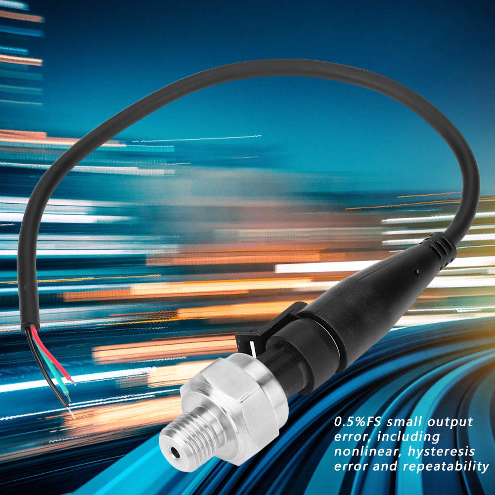
Figure 5.1: The sensor's output error specification of 0.5%FS, indicating its precision.
6. Maintenance
- Regular Inspection: Periodically inspect the sensor and its connections for any signs of damage, corrosion, or leaks.
- Cleaning: If necessary, gently clean the exterior of the sensor with a soft, damp cloth. Avoid using harsh chemicals or abrasive materials that could damage the stainless steel body or electrical components.
- Environmental Protection: While the sensor has a stainless steel body, ensure it is protected from extreme environmental conditions beyond its operating specifications.
- Storage: If storing the sensor, keep it in a dry, clean environment away from direct sunlight and extreme temperatures.

Figure 6.1: The stainless steel body of the sensor, highlighting its durable construction.
7. Troubleshooting
| Problem | Possible Cause | Solution |
|---|---|---|
| No Output Signal | No power supply; incorrect wiring; damaged sensor. | Check 5V DC power connection; verify wiring (Red to +5V, Black to GND, Green/White to Output); inspect sensor for physical damage. |
| Inaccurate Readings | Incorrect calibration; sensor not fully seated; air bubbles in fluid system; sensor range mismatch. | Perform system calibration; ensure sensor is properly installed and sealed; bleed air from fluid lines; confirm sensor's 0-10 PSI range is appropriate for your application. |
| Intermittent Signal | Loose wiring connections; electrical interference; faulty cable. | Secure all electrical connections; ensure proper shielding if interference is suspected; replace cable if damaged. |
| Leakage at Connection | Insufficient thread sealant; improper tightening. | Remove sensor, reapply thread sealant, and re-install with appropriate torque. |
Video 7.1: A brief overview of a 100 PSI pressure transducer sensor, demonstrating its physical characteristics. This video is provided by nineone.
8. Warranty and Support
For specific warranty information, please refer to the documentation provided with your purchase or contact the retailer directly. If you encounter any issues or require technical assistance, please reach out to the Walfront customer support or the seller from whom you purchased the product.
You can visit the official Walfront store for more product information: Walfront Store


