
1. Introduction
This manual provides detailed instructions for the Phoncoo Mini Data Logger Module (Model phElecF40328). This module is designed to facilitate data logging for projects utilizing platforms such as Arduino and Raspberry Pi. It features an SD card interface for data storage, a Real Time Clock (RTC) for accurate timestamping, and a 3.3V regulator for stable operation.
2. Product Overview
The Phoncoo Mini Data Logger Module is a compact and versatile solution for recording sensor data, environmental readings, or other project-specific information. Key features include:
- SD Card Interface: Compatible with FAT16 or FAT32 formatted SD cards for data storage.
- 3.3V Level Shifter: Integrated circuitry to prevent damage to your SD card from higher voltage microcontrollers.
- Real Time Clock (RTC): Keeps accurate time even when the main power is disconnected, requiring a separate battery (not included) for backup.
- Prototyping Area: Dedicated space for soldering additional connectors, custom circuitry, or sensors.
- Onboard 3.3V Regulator: Provides a stable reference voltage and ensures reliable power for SD cards.
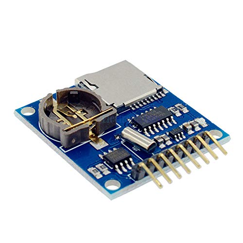
Figure 2.1: Top view of the Mini Data Logger Module, highlighting the SD card slot and the Real Time Clock (RTC) battery holder.
3. Setup
Follow these steps to set up your Mini Data Logger Module:
- Prepare SD Card: Format an SD card (up to 32GB recommended) to FAT16 or FAT32 file system. Insert the formatted SD card into the module's SD card slot.
- Install RTC Battery: The module requires a CR1220 coin cell battery (not included) for the Real Time Clock (RTC) to maintain time when external power is off. Carefully insert the battery into the RTC holder, ensuring correct polarity.
- Connect to Microcontroller: Connect the module to your Arduino or Raspberry Pi using the provided pin headers. Refer to the pinout diagram below for connections.

Figure 3.1: Pinout diagram of the Mini Data Logger Module. Ensure correct connections to your microcontroller.
Pin Connections:
- CS: Chip Select for SD card
- MOSI: Master Out Slave In (SPI data)
- MISO: Master In Slave Out (SPI data)
- SCK: Serial Clock (SPI clock)
- SCL: Serial Clock (I2C clock for RTC)
- SDA: Serial Data (I2C data for RTC)
- GND: Ground
- 5V: Power supply (typically 5V from Arduino/Raspberry Pi)
Software Setup:
To utilize the module, you will need to install the appropriate libraries for your microcontroller platform. For Arduino, this typically involves the SD library and an RTC library (e.g., RTClib). Example code is often provided with these libraries to help you get started with reading and writing data to the SD card and setting/reading the RTC.
4. Operating Instructions
Once the module is connected and software libraries are installed, you can begin logging data.
- Initialize SD Card: In your code, initialize the SD card using the appropriate library functions. Ensure the correct Chip Select (CS) pin is configured.
- Set/Read RTC: If this is the first time using the RTC or after a long power-off without battery, set the current time. Otherwise, read the current time from the RTC for timestamping your data.
- Log Data: Write your sensor readings or other data to a file on the SD card. It is recommended to include the timestamp from the RTC with each data entry for accurate record-keeping. Data can be written in various formats, such as CSV (Comma Separated Values) for easy parsing.
- Access Data: After logging, safely remove the SD card from the module. Insert the SD card into a computer to access the logged data files. These files can be opened with spreadsheet programs (e.g., Microsoft Excel, Google Sheets) or specialized plotting/analysis software.
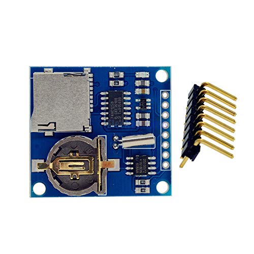
Figure 4.1: The Mini Data Logger Module with pin headers, illustrating its readiness for integration into a project.
5. Maintenance
Proper maintenance ensures the longevity and reliable operation of your data logger module.
- SD Card Handling: Always ensure the microcontroller is powered off or the SD card is properly unmounted via software before removing it to prevent data corruption.
- RTC Battery Replacement: The RTC battery (CR1220) has a lifespan of several years. If the RTC consistently loses time when the module is unpowered, replace the battery.
- Cleaning: Keep the module free from dust and debris. Use a soft, dry brush or compressed air for cleaning. Avoid using liquids or harsh chemicals.
- Storage: Store the module in a dry, anti-static environment when not in use.
6. Troubleshooting
If you encounter issues with your data logger module, consider the following:
- SD Card Not Detected:
- Ensure the SD card is properly inserted and formatted to FAT16/FAT32.
- Verify all pin connections (CS, MOSI, MISO, SCK, 5V, GND) are correct and secure.
- Check your code for correct SD card initialization and CS pin definition.
- Try a different SD card.
- RTC Not Keeping Time:
- Ensure a fresh CR1220 battery is correctly installed with proper polarity.
- Verify I2C connections (SCL, SDA, 5V, GND) for the RTC.
- Check your code for correct RTC initialization and time setting.
- Data Corruption:
- Always ensure the SD card is safely unmounted or the power is off before removal.
- Ensure stable power supply to the module.
- Module Not Powering On:
- Verify 5V and GND connections from your microcontroller.
- Check for any short circuits on the module.
7. Specifications
| Feature | Specification |
|---|---|
| Model Number | phElecF40328 |
| Manufacturer | Phoncoo |
| SD Card Compatibility | FAT16 or FAT32 formatted cards |
| RTC Battery Type | CR1220 (not included) |
| Operating Voltage | 5V (from microcontroller) |
| Onboard Regulator | 3.3V |
| Interface | SPI (for SD card), I2C (for RTC) |
8. Warranty and Support
For technical support or inquiries regarding the Phoncoo Mini Data Logger Module, please refer to the vendor's documentation or contact your point of purchase. Specific warranty details may vary by region and retailer.