
Introduction
This Operator's Manual provides essential information for the proper operation, basic maintenance, and adjustment of the Massey Ferguson MF 180 Tractor. It includes details on fluid types, quantities, and routine adjustments necessary for optimal performance and longevity of your equipment. Familiarize yourself with this manual before operating the tractor to ensure safe and efficient use.
Controls and Instruments
The controls and instruments on the MF 180 Tractor are designed for maximum operator comfort and convenience. All instruments are easily visible, and controls are within easy reach during operation.
Controls
Before operating the tractor, thoroughly review this section to become acquainted with all controls and their specific functions.

Figure 1: This image displays the left side of the Massey Ferguson MF 180 Tractor's control panel, highlighting the steering wheel, gear shift, and various levers for operational adjustments.

Figure 2: This image shows the right side of the Massey Ferguson MF 180 Tractor's control panel, including the ignition starter switch, differential lock, and other operational controls.
Ignition Starter Switch
For Diesel Models, the switch is turned to the 'Start' position to engage the starter. After the engine starts, it returns to 'Off' automatically. If the key is removed, the switch is locked in the 'Off' position.
For Gasoline Models, the switch has three positions: 'Off', 'Ignition', and 'Start'. Rotating to 'Ignition' activates the ignition system. Further rotation to 'Start' engages the starter. After the engine starts, the switch automatically returns to 'Ignition'. To stop the tractor, rotate the switch to the 'Off' position.
Steering Wheel and Column
The steering wheel and column are designed for operator comfort. The steering column can be telescoped to various heights and tilted to different angles, as shown in Figure 1.
Throttle Control Lever
Moving the throttle control lever forward increases engine speed, while moving it rearward decreases engine speed, as indicated in Figure 1.
Instruments
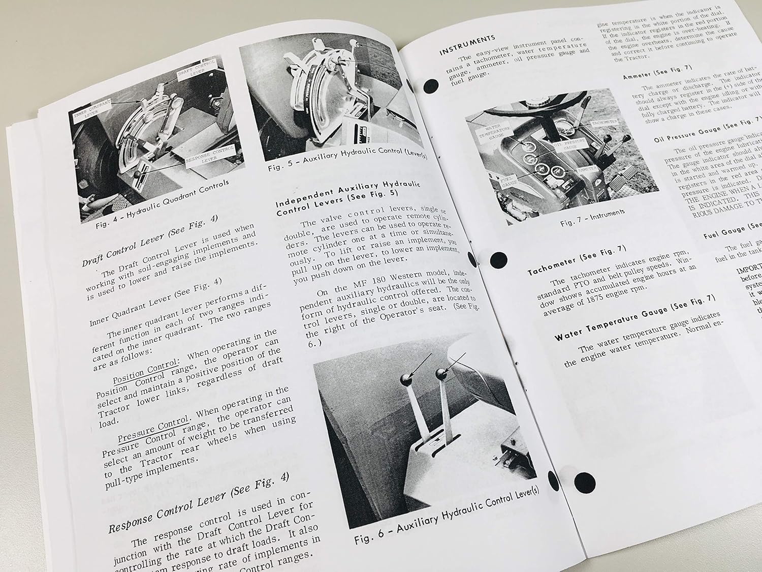
The instrument panel provides vital information about the tractor's operating status.
Tachometer
Indicates engine RPM and PTO speed. The average engine speed at 1875 RPM is shown in Figure 7 (refer to manual for exact figure).
Water Temperature Gauge
Displays the engine's coolant temperature. Normal operating temperature is crucial for engine health, as shown in Figure 7 (refer to manual for exact figure).
Oil Pressure Gauge
Monitors engine oil pressure. A low pressure reading indicates a potential issue, as shown in Figure 7 (refer to manual for exact figure).
Ammeter
Shows the rate of battery charge or discharge. A discharge reading indicates the battery is not being charged, as shown in Figure 7 (refer to manual for exact figure).
Operation
Pre-Starting Inspection
- Check fluid levels (engine oil, coolant, hydraulic fluid, fuel).
- Inspect tires for proper inflation and damage.
- Ensure all safety guards are in place.
- Verify all controls are in neutral or park position.
Starting the Engine
Warm Weather Starting
Ensure the transmission is in neutral. Turn the ignition key to the 'Start' position until the engine fires. Release the key immediately.
Cold Weather Starting (Gas and Diesel)
For diesel models, use the glow plug pre-heat if equipped. For both, ensure a fully charged battery. Use appropriate cold-weather starting aids if necessary.
Tractor Warm-Up Period
Allow the engine to warm up at a moderate RPM for a few minutes before engaging in heavy work. This ensures proper lubrication and engine performance.
Operating the Tractor
Break-In Procedure
During the initial hours of operation, avoid prolonged full-throttle use and sudden heavy loads. Vary engine speed and load to allow components to seat properly.
Selecting Ground Speeds
Choose appropriate gears based on terrain, load, and desired speed. Refer to the gear selection chart in the full manual.
Shifting Gears
Always depress the clutch fully when shifting gears. Shift smoothly to prevent wear on the transmission components.
Stopping the Tractor
Reduce engine speed, depress the clutch, apply brakes, and shift to neutral. Engage the parking brake. Turn off the engine using the ignition switch.
Towing the Tractor
When towing, ensure the transmission is in neutral and the parking brake is disengaged. Use a rigid tow bar and ensure the towed tractor's brakes are functional.
Multi-Power Transmission
If equipped, the Multi-Power transmission allows on-the-go shifting between high and low ranges within each gear. Consult the specific instructions for its use.
Test for Overload
Monitor engine sound and performance. If the engine struggles or RPM drops significantly, reduce the load or shift to a lower gear to prevent damage.
Hydraulic System
The MF 180 Tractor features a versatile hydraulic system for implement control.
When To Use Draft Control
Draft control is used for ground-engaging implements to maintain a consistent working depth by automatically adjusting the implement based on soil resistance.
Using Draft Control Lever
The draft control lever (Figure 4, refer to manual) adjusts the sensitivity of the draft control system.
When To Use Response Control
Response control adjusts the speed at which the implement reacts to changes in draft or position.
Using Response Control
The response control lever (Figure 4, refer to manual) allows fine-tuning of the implement's reaction speed.
Inner Quadrant Control
The inner quadrant lever (Figure 4, refer to manual) provides additional control over hydraulic functions, often used in conjunction with other levers.
When to Use Position Control
Position control is used to maintain a specific height or position for implements, independent of soil resistance.
Using Position Control
The position control lever (Figure 4, refer to manual) sets and maintains the desired implement height.
When to Use Pressure Control
Pressure control is used to transfer weight from the implement to the tractor's rear wheels, improving traction for pull-type implements.
Using Pressure Control
The pressure control lever (Figure 4, refer to manual) adjusts the amount of weight transfer.
Pull-Type Implements
Constant Pumping Range
This setting ensures continuous hydraulic flow for implements requiring constant power, such as hydraulic motors.
Auxiliary Hydraulic System
Basic Auxiliary Hydraulic System
Provides hydraulic power to external implements via remote couplers.
Independent Auxiliary Hydraulic System
If equipped, this system offers dedicated hydraulic flow independent of the main lift system, often with its own control levers (Figure 5, refer to manual).
Operating Auxiliary Hydraulics
Lock-Out and Variable Drop Cartridge (Accessory)
This accessory allows for locking the hydraulic lift in a specific position or controlling the drop rate of implements.
Connecting Hoses to Quick-Couplers
Ensure quick-couplers are clean before connecting hydraulic hoses. Push hoses firmly into couplers until they lock into place. Verify a secure connection before operation.
Attaching and Detaching Implements
Attaching 3-Point Hitch Implements
Position the tractor to align with the implement's lower links. Connect the lower links first, then the top link. Secure all pins with linchpins. Adjust the top link for proper implement angle.

Figures 36-40: This image illustrates various steps and components for attaching pull-type implements, including coupler frame positions, installing coupler chains, and chain spreader details.
Detaching 3-Point Hitch Implements
Lower the implement to the ground. Remove the top link, then the lower links. Ensure the implement is stable before moving the tractor.
Attaching Pull-Type Pressure Control Implements
Connect the drawbar to the implement. Ensure the pressure control system is correctly engaged to transfer weight to the tractor's rear wheels.
Attaching 3-Point Hitch Implements Using Rapid Coupler
Align the rapid coupler with the implement's attachment points. Engage the coupler by backing the tractor carefully. Ensure all latches are securely engaged. Important: If latches are not engaged correctly, they are liable to shear, resulting in damage.

Figures 42-44: This image shows the implement attached to a rapid coupler, the universal swinging drawbar, and the adjustable top link, detailing their connection and function.
Swinging Drawbar
The universal swinging drawbar (Figure 43) allows for flexibility in towing. Ensure it is locked in the desired position for operation.
Adjustable Top Link
The adjustable top link (Figure 44) is used to set the pitch of 3-point hitch implements. Adjust it to achieve the correct working angle. Caution: Never pull from the PTO driven implement's top link. Always pull from the drawbar. Practice safety.
Power Take-Off (PTO)
The PTO provides power to various implements. Ensure the PTO shaft is properly guarded and engaged only when the implement is ready for operation.
"Live" Power Take-Off
A live PTO operates independently of the clutch, allowing the operator to stop the tractor without disengaging the PTO.
"Independent" Power Take-Off
An independent PTO has its own clutch, allowing it to be engaged or disengaged regardless of the tractor's movement or main clutch.
Stopping the Tractor
To stop the tractor, disengage the PTO (if active), reduce engine speed, depress the clutch, apply brakes, shift to neutral, engage the parking brake, and turn off the ignition.
Operating Adjustment
Wheels and Tires
Front Wheel Tread Widths
Adjust front wheel tread widths to match rear wheel settings and ensure stability for specific tasks. Refer to the manual for recommended settings.
Rear Wheel Tread Widths
Rear wheel tread widths can be adjusted for stability, traction, and to match row spacing for cultivation. Important: When adjusting the rear wheel tread, the fenders may need to be removed. Ensure the wheels are properly secured after adjustment. Caution: Never use makeshift jacks when lifting the tractor. Use a proper jack that will safely support the tractor. Always block the tractor for added protection. Practice safety.
Figures 53-58: This image illustrates adjustments for the PAVT rear wheel, Float-O-Matic seat positions (sitting and standing), steering column tilt and telescoping, and fender adjustments.
Float-O-Matic Seat
The Float-O-Matic seat (Figures 54 and 55) offers adjustable comfort. Adjust the seat for height, fore-and-aft position, and weight to suit the operator and reduce fatigue during long operating periods.
Steering Column Adjustment
The steering column (Figures 56 and 57) can be tilted and telescoped to provide an ergonomic operating position, whether sitting or standing.
Fender Adjustment
Fenders (Figure 58) can be adjusted to provide adequate clearance and protection from mud and debris. Ensure they are securely fastened after adjustment.
Liquid Filling the Tires
Liquid ballast can be added to tires to increase traction and stability. Use calcium chloride solution for cold weather. Refer to the manual for correct quantities and procedures.
Fuel and Fuel Care
Fuels
Gasoline Engine
Use unleaded gasoline with the recommended octane rating. Avoid using fuels with excessive ethanol content unless specified.
Diesel Engine
Use high-quality diesel fuel. Ensure fuel is clean and free of water and contaminants. Use winter-grade diesel in cold climates to prevent gelling.
Fuel Care
Store fuel in clean, approved containers. Keep fuel tanks full to minimize condensation. Regularly drain water and sediment from the fuel tank and filter.
Lubricants and Lubrication
General Information
Proper lubrication is critical for the longevity and performance of your tractor. Use only recommended lubricants.
Storing Lubricants
Store lubricants in clean, sealed containers in a cool, dry place to prevent contamination.
Lubrication Symbols
Familiarize yourself with the lubrication symbols used in this manual to identify different lubrication points and types.
Lubricants and Capacities
Refer to the detailed chart in the full manual for specific lubricant types (engine oil, hydraulic fluid, transmission fluid, grease) and their required capacities for various components.
Maintenance and Servicing
Maintenance Schedule
Adhere to the following maintenance schedule to ensure reliable operation:
- Each 10 Hours or Daily Maintenance: Check engine oil level, coolant level, tire pressure, and inspect for leaks.
- At 2 and 10 Hours of Operation When New: Perform initial checks as specified in the manual.
- Daily for First 14 Days of Operation: Conduct daily checks and monitor for any unusual operation.
- Each 50 Hours or Break-In: Change engine oil and filter, check all fluid levels, lubricate grease points.
- Each 100 Hour Maintenance: Inspect fan belt tension, clean air filter, check battery terminals.
- Each 200 Hour Maintenance: Replace fuel filters, inspect hydraulic system, check brake adjustment.
- Each 750 Hours or Annually Maintenance: Change transmission and hydraulic fluid, inspect steering components, check wheel bearings.
Servicing
Diesel Fuel System
Regularly drain water from the fuel filter and replace fuel filters as per the maintenance schedule.
Gasoline Fuel System
Inspect fuel lines for leaks and replace fuel filters as needed.
Ignition System
Check spark plugs, ignition wires, and distributor (if applicable) for wear and proper function.
Air Filter
Clean or replace the air filter element regularly, especially when operating in dusty conditions.
Electrical System
Inspect battery terminals, wiring, and lights. Ensure all electrical connections are secure and free of corrosion.
Fan Belt
Check fan belt tension and condition. Adjust or replace if worn or loose.
Safety Flashing Amber Light
Verify the safety flashing amber light is operational for visibility.
Cooling System
Maintain proper coolant level and concentration. Clean radiator fins and inspect hoses for leaks or damage.
Clutch Adjustment
Ensure proper clutch free play. Adjust as necessary to prevent premature wear.
Differential Lock
Check the differential lock for proper engagement and disengagement.
Brake Adjustment
Adjust brakes to ensure even and effective stopping power. Check brake fluid level if applicable.
Front Wheel Alignment
Periodically check front wheel alignment to ensure even tire wear and proper steering.
Re-Packing Front Wheel Bearings
Inspect and re-pack front wheel bearings with grease as per the maintenance schedule.
Hydraulic Control Quadrant
Ensure smooth operation of the hydraulic control levers and quadrant.
Throttle Control Lever
Check for smooth operation and proper tension of the throttle control lever.
Rear Wheels
Inspect rear wheels for damage and ensure lug nuts are tightened to specification.
Power Steering
Check power steering fluid level and inspect hoses for leaks. Ensure smooth and responsive steering.
Rear Axle Planetary
If equipped, check the oil level in the rear axle planetary drives and change oil as recommended.
Tractor Storage
For extended storage, clean the tractor thoroughly, perform all necessary maintenance, and protect exposed metal surfaces. Disconnect the battery and store it in a cool, dry place. Fill the fuel tank to prevent condensation and add fuel stabilizer. Cover the tractor to protect it from elements.
Troubleshooting
This section provides guidance for common operational issues. For complex problems, consult a qualified service technician.
- Engine Fails to Start: Check fuel level, battery charge, ignition system, and fuel filters.
- Loss of Hydraulic Power: Check hydraulic fluid level, filter, and pump operation.
- Overheating Engine: Check coolant level, radiator cleanliness, fan belt tension, and thermostat.
- Poor Braking Performance: Inspect brake adjustment, pads/shoes, and hydraulic system (if applicable).
Accessories
A range of accessories is available to enhance the functionality of your MF 180 Tractor. Consult your dealer for compatible attachments and options.
Specifications
The Massey Ferguson MF 180 Tractor is manufactured by AgPubs. For detailed technical specifications, refer to the comprehensive tables in the full manual.
- Manufacturer: AgPubs
- ASIN: B07KGHXK6M
Warranty and Support
This manual is a quality reproduction designed to be more durable than the original print. For specific warranty information regarding the manual itself or for product support inquiries, please contact AgPubs or your authorized dealer. Factory OEM authored manuals are generally superior to aftermarket versions for accurate information and DIY savings.