
Eventek ET580
Eventek ET580 Digital Multimeter User Manual
Model: ET580
Brand: Eventek

Front view of the Eventek ET580 Digital Multimeter with its red and black test leads, displaying a reading on its LCD screen.
Introduction
The Eventek ET580 Digital Multimeter is a versatile and reliable instrument designed for measuring AC/DC voltages, AC/DC currents, resistance, continuity, and diode functionality. It features auto-ranging capabilities, overload protection, and a large backlit LCD for clear readings. This manual provides detailed instructions for the safe and effective use of your ET580 multimeter.

This image collage demonstrates the Eventek ET580 Digital Multimeter being used in various applications, including testing circuit boards, automotive components, motorcycle electronics, and household electrical systems.
Safety Information
Always observe basic safety precautions when using this multimeter to avoid personal injury or damage to the instrument.
- Do not exceed the maximum input values specified for each measurement range.
- Never apply voltage to the meter when the rotary switch is set to current, resistance, diode, or continuity functions.
- Ensure the test leads are properly connected and the rotary switch is set to the correct function before making any measurements.
- Be cautious when working with live circuits. Use appropriate personal protective equipment (PPE).
- Do not use the meter if it appears damaged or if the test leads are frayed.
- Replace batteries promptly when the low battery indicator appears to ensure accurate readings.
Product Overview
Familiarize yourself with the components of your Eventek ET580 Digital Multimeter.

This image shows the front view of the Eventek ET580 Digital Multimeter with various parts labeled, including the LCD display, Select Button, Range button, Rotary switch, 10A jacks, NCV/LINE LED Indicator, Backlit button, Data hold button, COM jack, and VΩmA Jack.
Key Components
- LCD Display: Shows measurement readings, units, and function indicators.
- Rotary Switch: Used to select the desired measurement function (e.g., V~, V-, A~, A-, Ω, Diode, NCV).
- SELECT Button: Shifts measurements for AC/DC current, temperature, diode, and continuity check within a function.
- RAN (Range) Button: Toggles between auto-ranging and manual ranging modes.
- HOLD Button: Freezes the current reading on the display.
- Backlight Button: Activates or deactivates the LCD backlight.
- NCV/LINE LED Indicator: Illuminates during Non-Contact Voltage detection.
- COM Jack: Common (negative) input terminal for all measurements. Connect the black test lead here.
- VΩmA Jack: Positive input terminal for voltage, resistance, diode, continuity, and small current measurements. Connect the red test lead here.
- 10A Jack: Positive input terminal for high current (up to 10A) measurements. Connect the red test lead here for 10A measurements.

This image displays the back of the Eventek ET580 Digital Multimeter, highlighting its convenient hook hole for hanging in various workplaces and the integrated support frame for angled viewing on a flat surface.
Setup
Battery Installation
- Ensure the multimeter is turned OFF.
- Locate the battery compartment cover on the back of the unit.
- Use a screwdriver to remove the screw securing the battery cover.
- Insert two 1.5V AAA batteries, observing the correct polarity (+/-) as indicated inside the compartment.
- Replace the battery cover and secure it with the screw.
Connecting Test Leads
- Insert the black test lead into the COM (Common) jack.
- For most measurements (voltage, resistance, diode, continuity, small current), insert the red test lead into the VΩmA jack.
- For high current measurements (up to 10A), insert the red test lead into the 10A jack.
Operating Instructions
General Operation
- Turn the rotary switch from the OFF position to the desired measurement function.
- The ET580 features auto-ranging, automatically selecting the appropriate range for the measurement. You can press the RAN button to switch to manual ranging if needed.
- Press the Backlight button to illuminate the LCD display in low-light conditions.
Measuring DC Voltage (V-)
- Set the rotary switch to the V- position.
- Connect the black test lead to the COM jack and the red test lead to the VΩmA jack.
- Connect the test probes in parallel across the DC voltage source to be measured.
- Read the voltage value on the LCD display.
Measuring AC Voltage (V~)
- Set the rotary switch to the V~ position.
- Connect the black test lead to the COM jack and the red test lead to the VΩmA jack.
- Connect the test probes in parallel across the AC voltage source to be measured.
- Read the voltage value on the LCD display.
Measuring DC Current (A-)
- Set the rotary switch to the A- or mA- position. Use the SELECT button to choose the appropriate range (µA, mA, or A).
- For currents up to 200mA, connect the black test lead to the COM jack and the red test lead to the VΩmA jack.
- For currents up to 10A, connect the black test lead to the COM jack and the red test lead to the 10A jack.
- Connect the multimeter in series with the circuit where current is to be measured.
- Read the current value on the LCD display.
Measuring AC Current (A~)
- Set the rotary switch to the A~ or mA~ position. Use the SELECT button to choose the appropriate range (µA, mA, or A).
- For currents up to 200mA, connect the black test lead to the COM jack and the red test lead to the VΩmA jack.
- For currents up to 10A, connect the black test lead to the COM jack and the red test lead to the 10A jack.
- Connect the multimeter in series with the circuit where current is to be measured.
- Read the current value on the LCD display.
Measuring Resistance (Ω)
- Set the rotary switch to the Ω position.
- Connect the black test lead to the COM jack and the red test lead to the VΩmA jack.
- Ensure the circuit or component is de-energized before measuring resistance.
- Connect the test probes across the component to be measured.
- Read the resistance value on the LCD display.
Diode and Continuity Test
- Set the rotary switch to the Diode/Continuity position. Use the SELECT button to toggle between diode test and continuity test.
- Connect the black test lead to the COM jack and the red test lead to the VΩmA jack.
- For Diode Test: Connect the red probe to the anode and the black probe to the cathode of the diode. The display will show the forward voltage drop. Reverse the probes to check for open circuit.
- For Continuity Test: Connect the probes across the circuit or component. If resistance is less than approximately 70Ω, the buzzer will sound, indicating continuity.
NCV (Non-Contact Voltage) Detection
The NCV function allows for non-contact detection of AC voltage, enhancing safety by identifying live wires without direct contact.
- Set the rotary switch to the NCV position.
- Move the top end of the multimeter (where the NCV sensor is located) close to the conductor or outlet you suspect has AC voltage.
- If AC voltage is detected, the NCV indicator light will flash, and the buzzer will emit an audible alarm (di-di-di).
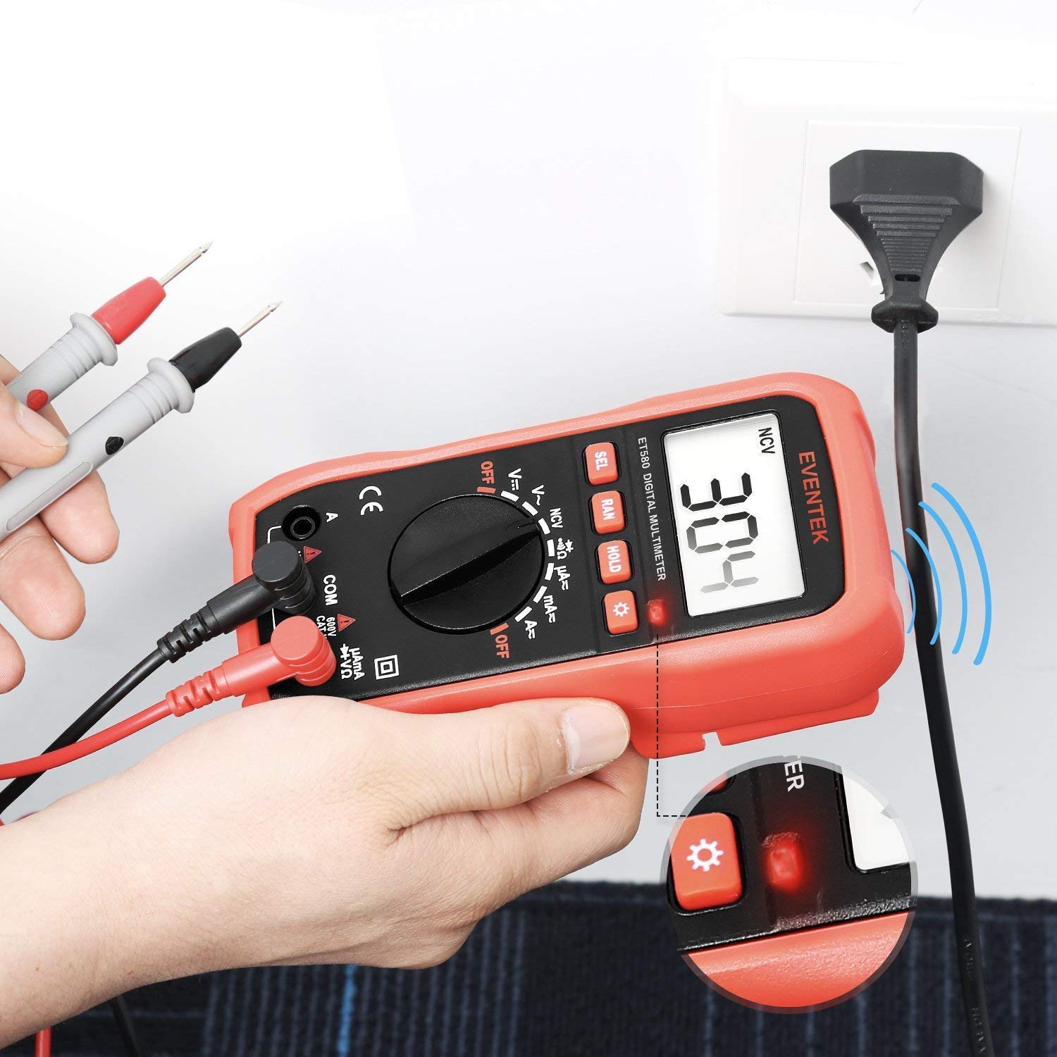
This image illustrates the NCV detection feature of the Eventek ET580 Digital Multimeter. The top of the meter is held near a power cord, and the display shows a reading, indicating the presence of voltage without direct contact. The NCV indicator light is also shown.
Data Hold Function
The data hold function allows you to freeze the current reading on the display for easier viewing, especially in hard-to-reach areas.
- While taking a measurement, press the HOLD button. The current reading will be frozen on the LCD, and a 'HOLD' indicator will appear.
- Press the HOLD button again to release the reading and return to live measurement mode.

This image shows two scenarios: on the left, the multimeter is measuring a 9V battery, and the 'HOLD' button is highlighted, indicating the data hold function is active. On the right, the multimeter is measuring an AC outlet, demonstrating its versatility.
Maintenance
Cleaning
- Turn off the multimeter and disconnect all test leads before cleaning.
- Wipe the case with a damp cloth and a mild detergent. Do not use abrasives or solvents.
- Ensure the meter is completely dry before use.
Battery Replacement
When the low battery indicator appears on the display, replace the batteries promptly to ensure accurate readings and proper operation. Follow the battery installation steps in the Setup section.
Storage
- If the multimeter will not be used for an extended period, remove the batteries to prevent leakage.
- Store the meter in a cool, dry place, away from direct sunlight and extreme temperatures.
Troubleshooting
| Problem | Possible Cause | Solution |
|---|---|---|
| No display or dim display | Dead or low batteries; Incorrect battery polarity | Replace batteries; Check battery orientation |
| Incorrect readings | Incorrect function selected; Loose test leads; Overload; Damaged fuse (for current) | Select correct function; Reconnect leads firmly; Check input limits; Replace fuse if blown |
| No continuity beep | Circuit resistance too high; Function not set to continuity | Ensure resistance is below 70Ω; Select continuity function |
| NCV not detecting | No AC voltage present; Sensor not close enough | Verify AC voltage presence; Move sensor closer to source |
Specifications
| Measurement Type | Range | Accuracy |
|---|---|---|
| DC Voltage | 200mV / 2V / 20V / 200V / 500V | ±(0.5% + 2 digits) |
| AC Voltage | 200mV / 2V / 20V / 200V / 500V | ±(1.0% + 10 digits) |
| DC Current | 200µA / 2mA / 20mA / 200mA / 2A / 10A | ±(1.0% + 5 digits) for 200µA-2A, ±(2.5% + 5 digits) for 10A |
| AC Current | 200µA / 2mA / 20mA / 200mA / 2A / 10A | ±(1.8% + 5 digits) for 200µA-20mA, ±(2.5% + 5 digits) for 200mA-10A |
| Resistance | 200Ω / 2kΩ / 20kΩ / 200kΩ / 2MΩ / 20MΩ | ±(1.0% + 2 digits) for 200Ω-2MΩ, ±(1.5% + 2 digits) for 20MΩ |
| Display | 3 1/2 digit LCD, 2000 counts | N/A |
| Power Supply | 2 x 1.5V AAA Battery | N/A |
| Dimensions | 160 x 130 x 48mm (6.3 x 5.1 x 1.9in) | N/A |
| Weight | 250g (0.55lb) | N/A |
What's in the Box
Your Eventek ET580 Digital Multimeter package includes:
- 1 x Eventek ET580 Digital Multimeter
- 1 pair x Test Leads (Red and Black)
- 2 x AAA 1.5V Batteries (pre-installed or included separately)
- 1 x User Manual (this document)

This image displays the items included in the Eventek ET580 Digital Multimeter package: the multimeter itself, a user manual, test leads, and the product box.
Warranty and Support
Eventek products are designed for reliability and performance. For any questions, technical support, or warranty inquiries, please refer to the contact information provided with your purchase or visit the official Eventek website.
Ask a question about this manual
Ask about setup, troubleshooting, compatibility, parts, safety, or missing instructions. Manuals+ will review the question and use this page’s manual context to help answer it.