Introduction
This service manual provides comprehensive instructions for the Massey Ferguson 35 Loader Attachment 100. It covers essential information regarding the hydraulic system, including specifications, setup, maintenance, and troubleshooting procedures. Adherence to these guidelines ensures proper operation and longevity of the equipment.
Setup and Installation
Proper setup of the hydraulic system is crucial for the Massey Ferguson 35 Loader Attachment. Pay close attention to the hydraulic pump installation and connections.
Hydraulic Pump Installation Briefs:
- The pump diaphragm and thrust plate must be installed with the bronze side facing the gear faces.
- Ensure the thrust plate's mid-section cut-away is positioned on the suction side of the pump.
For detailed hydraulic pump specifications, refer to the 'Specifications' section.
Operation
The Massey Ferguson 35 Loader Attachment is designed for efficient material handling. Familiarize yourself with the loader controls and hydraulic system response before operating. Always ensure the attachment is securely mounted and all hydraulic connections are tight and free from leaks. Operate the loader on stable, level ground and avoid exceeding its rated capacity.
Maintenance
Regular maintenance is essential for the reliable performance of your Massey Ferguson 35 Loader Attachment. Focus on the hydraulic system components, including the pump and associated lines.
Hydraulic System Checks:
- Periodically inspect all hydraulic lines and fittings for wear, damage, or leaks.
- Check hydraulic fluid levels and quality regularly. Refer to your tractor's manual for recommended fluid types and change intervals.
- Ensure the hydraulic pump diaphragm and thrust plate are correctly seated as per installation briefs.
- Monitor pump performance for any unusual noises or reduced efficiency.
Troubleshooting Hydraulic Systems
This section provides guidance for diagnosing and resolving common issues within the hydraulic system of your loader attachment.
Using a Flow Tester:
A flow tester is a valuable tool for diagnosing hydraulic system performance. Two primary methods are described:
- Parallel - Before Control Valve Method:
If the loader control valve has a 1/4 inch pipe plug in its base, connect the flow tester's inlet port either into the system between the pump and the control valve, or to the 1/4 inch pipe fitting at the base of the control valve. The outlet port of the flow tester should connect directly to the reservoir. Before performing a pump efficiency test with this setup, determine the relief valve opening pressure to avoid misattributing gallonage loss to the relief valve. - Parallel - After Control Valve Method:
Connect the flow tester's inlet port to a port of the control valve leading to a cylinder. The outlet port of the flow tester should connect to either the control valve's other port (within the same circuit as the inlet) or directly to the reservoir. As with the 'before control valve' method, determine the relief valve opening pressure before conducting a pump efficiency test.
The 'parallel-before control valve method' is generally suggested if the loader control valve contains a 1/4 inch pipe plug in its base.
Connecting a Pressure Gauge:
A pressure gauge can be used to assess maximum available pressures, main relief valve opening pressure, and to identify cylinder leak-down issues (faulty packing or internal leakage past the control valve). Note that pump gallonage cannot be checked with a pressure gauge.
Connect the pressure gauge into the hydraulic system either between the pump and the control valve, or directly into the cylinder circuit.

This image displays instructions and diagrams for troubleshooting and testing hydraulic systems on the Massey Ferguson 35 Loader Attachment. It includes diagrams for 'Parallel - Before Control Valve Method of Flow Tester Connection' and 'Parallel - After Control Valve Method of Flow Tester Connection'. A photograph shows a 'Typical Connection of Flow Tester in Parallel - Before Control Valve' on the actual equipment. Text describes the procedure for using a flow tester to diagnose hydraulic issues and connecting a pressure gauge.
Specifications
This section details the general product specifications and specific hydraulic pump specifications for the Massey Ferguson 35 Loader Attachment 100.
General Product Specifications:
- Manufacturer: Jensales
- Part Number: MH-S-MF100LDR+{517396}
- Product Dimensions: 12 x 10 x 3 inches
- Item Model Number: 35
- ASIN: B07JYQJLR5
- Date First Available: February 15, 2019
Hydraulic Pump Specifications (MF Part No. 191 191 M91):
| Specification | Value |
|---|---|
| Manufacturer's Part No. (Cessna) | L 20112-1 DJH |
| Direction of Rotation (facing pump shaft end) | Counterclockwise |
| Mounting Bolts | 2 SAE No. size (1/2") |
| Inlet Port (suction) | 1-5/16" - 12 UN |
| Outlet Port (pressure) | 1-1/16" - 12 JIC |
| Displacement | 3.02 cu. in. per revolution |
| Gallonage @ 1800 rpm | 23.5 gpm @ 2000 psi |
| Gallonage @ 2000 rpm | 24 gpm @ 2125 psi |
| Gallonage @ 2200 rpm | 25 gpm @ 0 psi |
| Measurement of Gear Shafts in Bearing Areas | Minimum .873 inch |
| Measurement of Gear Widths | Minimum 1.517 inches |
| Measurement of Gear Pockets (outer body) | Maximum 3.101 inches |
| Measurement of Shaft Bearing (inner diameter) | Maximum .875 inch |
| Tie Bolt Torque | 60-65 ft.-lbs. |
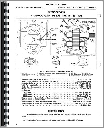
This image displays a detailed diagram of the hydraulic pump (MF Part No. 191 191 M91) for the Massey Ferguson 35 Loader Attachment. It includes an exploded view of the pump components with numbered parts and a cross-sectional view. Below the diagrams, specifications such as manufacturer (Cessna), direction of rotation, mounting bolts, port sizes, displacement, and pressure ratings are listed. Service briefs regarding pump diaphragm and thrust plate installation are also provided.
Warranty Information
For specific warranty details regarding your Jensales Massey Ferguson 35 Loader Attachment 100 Service Manual, please refer to the documentation provided at the time of purchase or contact Jensales directly. Warranty terms typically cover defects in materials and workmanship for a specified period.
Customer Support
Should you require further assistance, have questions about the service procedures, or need to order replacement parts, please contact Jensales customer support. Have your product model number (35) and part number (MH-S-MF100LDR+{517396}) ready for efficient service.
Jensales Contact Information:
Please visit the official Jensales website or refer to your purchase invoice for the most current contact details.


