1. Introduction
The KuWFi Gigabit PoE Network Switch (Model 901-AFG-411S) is designed to provide seamless network connectivity and Power over Ethernet (PoE) capabilities. It features a high-speed network IC and a stable PoE chip, supporting IEEE 802.3af and IEEE 802.3at standards. This switch automatically detects and supplies power to compatible powered devices (PDs) such as IP cameras and wireless access points, while non-PoE devices receive data only. It offers 10/100/1000M Ethernet connections for efficient data transfer.
2. Package Contents
Verify that all items are present in the package:
- KuWFi Gigabit PoE Network Switch (Model 901-AFG-411S)
- Power Cord
- User Manual
- Certification Card
3. Product Overview
3.1 Front Panel

Figure 1: Front view of the KuWFi Gigabit PoE Network Switch.
- PoE Ports (1-4): Four 10/100/1000M RJ45 ports with Power over Ethernet capabilities. These ports can supply power to IEEE 802.3af/at compliant devices. Port 1 supports BT 60W.
- Uplink RJ45 Port (5): One 1000M RJ45 port for connecting to a router, NVR, or main network.
- Uplink SFP Port (6): One 1000M SFP port for fiber optic uplink connections.
- PWR LED: Indicates power status. Lit when the switch is powered on.
- Mode LED: Indicates the current operating mode (VLAN, Default, Extend).
- Link/Act LEDs (per port): Indicates network link status and activity. Lit when a link is established, blinks during data transmission.
- DIP Switch: Used to select the operating mode of the switch.
3.2 Rear Panel

Figure 2: Rear view of the KuWFi Gigabit PoE Network Switch with power input.
- AC Input: Power connector for the included AC power cord (100-240V, 50/60Hz).
4. Setup Instructions
Follow these steps to set up your KuWFi Gigabit PoE Network Switch:
- Placement: Place the switch on a stable, flat surface in a well-ventilated area. Ensure there is adequate space around the device for heat dissipation.
- Connect Power: Connect the provided power cord to the AC input on the rear panel of the switch, then plug the other end into a standard AC power outlet. The PWR LED on the front panel should illuminate.
- Connect Uplink: Connect your router, NVR, or main network device to the Uplink RJ45 Port (Port 5) or the Uplink SFP Port (Port 6) using an appropriate Ethernet or fiber cable.
- Connect PoE Devices: Connect your PoE-powered devices (e.g., IP cameras, wireless access points) to any of the PoE Ports (Ports 1-4) using standard Ethernet cables. The switch will automatically detect and provide power to these devices.
- Connect Non-PoE Devices: If you have non-PoE network devices, you can also connect them to Ports 1-4. The switch will only transmit data to these devices without supplying power.
- Configure DIP Switch (Optional): Before connecting devices, you may adjust the DIP switch settings according to your network requirements. Refer to Section 5 for details on DIP switch modes.
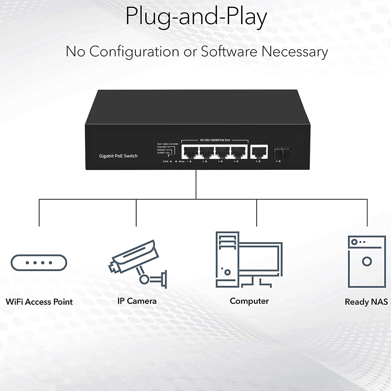
Figure 3: Plug-and-Play connectivity diagram.

Figure 4: Connecting an Ethernet cable to the switch.
5. Operating Instructions
5.1 DIP Switch Modes
The DIP switch on the front panel allows you to select different operating modes for the switch. Adjust the switch according to your network requirements.
- VLAN Mode: In this mode, PoE ports (1-4) are isolated from each other. They can only communicate with the Uplink ports (5 and 6). This enhances network security and prevents broadcast storms within the PoE network segment.
- Default Mode: This is the normal operating mode. All ports (1-6) can communicate with each other. The maximum transmission distance is within 100 meters.
- Extend Mode: In this mode, the PoE power supply and data transmission distance for ports 3 and 4 can be extended up to 250 meters. The transmission rate for these extended ports will be reduced to 10Mbps. This mode is useful for long-distance deployments of PoE devices.
5.2 Power over Ethernet (PoE) Functionality

Figure 5: Power and Data transmission over PoE.
The switch's PoE ports automatically detect and provide power to IEEE 802.3af/at compliant devices. This eliminates the need for separate power adapters for your PoE devices, simplifying installation and reducing cable clutter. Port 1 is capable of supplying up to 60W for high-power PoE devices.
6. Maintenance
To ensure optimal performance and longevity of your KuWFi Gigabit PoE Network Switch, follow these maintenance guidelines:
- Cleaning: Regularly clean the exterior of the switch with a soft, dry cloth. Do not use liquid or aerosol cleaners.
- Ventilation: Ensure that the ventilation openings on the switch are not blocked. Proper airflow is crucial for heat dissipation.
- Environment: Operate the switch within the recommended temperature and humidity ranges (refer to Specifications). Avoid exposing the device to direct sunlight, excessive heat, or moisture.
- Cable Management: Keep network cables organized and free from kinks or excessive bending to prevent signal degradation.

Figure 6: Fanless design for silent operation.

Figure 7: Operating temperature range.
7. Troubleshooting
If you encounter issues with your KuWFi Gigabit PoE Network Switch, refer to the following common problems and solutions:
- No Power:
- Ensure the power cord is securely connected to both the switch and the power outlet.
- Verify that the power outlet is functional.
- Check if the PWR LED on the front panel is illuminated.
- No Link/Activity on a Port:
- Check the Ethernet cable connection between the switch and the connected device. Try a different cable.
- Ensure the connected device is powered on and functioning correctly.
- Verify that the Link/Act LED for that specific port is lit or blinking.
- If connecting a PoE device, ensure it is IEEE 802.3af/at compliant and not drawing excessive power beyond the port's capacity.
- Slow Network Speed:
- Ensure all connected devices and cables support Gigabit Ethernet (1000Mbps).
- Check the DIP switch setting. If in Extend Mode, ports 3 and 4 operate at 10Mbps.
- Verify that the uplink connection to your router or main network is also operating at Gigabit speed.
- Avoid network congestion by ensuring proper network design.
- PoE Device Not Receiving Power:
- Confirm the device is a Power over Ethernet (PoE) device and is compliant with IEEE 802.3af or 802.3at standards.
- Ensure the total power consumption of all connected PoE devices does not exceed the switch's power budget.
- Try connecting the PoE device to a different PoE port.
8. Specifications
| Feature | Description |
|---|---|
| Model | 901-AFG-411S |
| Ports | 4x 10/100/1000M PoE RJ45 Ports, 1x 1000M RJ45 Uplink Port, 1x 1000M SFP Uplink Port |
| PoE Standards | IEEE 802.3af (15.4W), IEEE 802.3at (30W) |
| PoE Port 1 Output | BT 60W |
| Network Standards | IEEE 802.3, IEEE 802.3u, IEEE 802.3ab, IEEE 802.3z, IEEE 802.3x |
| Switching Capacity | 12Gbps |
| Transfer Mode | Store and Forward |
| Flow Control | Full-duplex: IEEE 802.3x, Half-duplex: Back pressure |
| Auto MDI/MDIX | Supported |
| DIP Switch Modes | VLAN, Default, Extend |
| Power Input | AC 100-240V, 50/60Hz |
| Product Dimensions (L*W*H) | 200mm * 118mm * 44mm (7.87"L x 4.65"W x 1.73"H) |
| Net Weight | 0.6 kg (1.32 lbs) |
| Operating Temperature | -10°C to 55°C |

Figure 8: 12Gbps Switching Capacity.
9. Warranty Information
This product is covered by a standard manufacturer's warranty. Please refer to the warranty card included in your package for specific terms and conditions. Keep your purchase receipt as proof of purchase for warranty claims.
10. Support
For technical assistance or customer support, please refer to the contact information provided on the product packaging or the official KuWFi website. When contacting support, please have your product model number (901-AFG-411S) and purchase details ready.


