1. Introduction
This manual provides essential instructions for the proper installation, operation, and maintenance of the VTSYIQI Ultrasonic Flow Meter TL-1-HT. To ensure accurate measurements and safe operation, please read this manual thoroughly before using the device and retain it for future reference.
The VTSYIQI TL-1-HT is designed for measuring the flow velocity of liquids in pipes ranging from DN300 to DN6000mm using a waterproof clamp-on transducer. It offers high accuracy and bi-directional measurement capabilities.
2. Safety Information
Observe the following safety precautions to prevent injury and damage to the instrument:
- Ensure the power supply voltage matches the instrument's requirements (DC8~36V or AC85~264V).
- Do not operate the device in environments with flammable or explosive gases.
- Avoid exposing the main unit to excessive moisture or direct water spray, although transducers are waterproof.
- All wiring should be performed by qualified personnel following local electrical codes.
- Do not attempt to disassemble or repair the instrument yourself. Contact authorized service personnel for assistance.
- Handle transducers and cables with care to prevent damage.
3. Product Overview
3.1 Key Features
- Accuracy: ±1%
- Velocity Range: 0 to ±10m/s, bi-directional measurement
- Pipe Size: DN300-6000mm (11.81-236.22 inches)
- Temperature Range: -30°C to 160°C
- Liquid Compatibility: Single liquids capable of transmitting ultrasound (e.g., water, seawater, sewage, oil).
- Pipe Material: Steel, stainless steel, cast iron, copper, PVC, aluminum, glass steel, etc. Liner is allowed.
- Signal Output: 1 way 4-20mA, 1 way OCT pulse, 1 way Relay output
- Signal Input: 3 way 4-20mA input, supports heat measurement via PT100 platinum resistor.
- Interface: RS485, supports MODBUS protocol.
- Power Supply: DC8~36V or AC85~264V
3.2 Components
The VTSYIQI TL-1-HT Ultrasonic Flow Meter system typically includes the following components:
- Main Flow Meter Unit (with display and control buttons)
- Waterproof Clamp-on Transducers (TL-1-HT type)
- Transducer Cables
- Mounting Clamps/Straps for Transducers

Figure 1: Front view of the VTSYIQI Ultrasonic Flow Meter main unit, showing the display and control buttons (MENU, UP, DOWN, ENT).

Figure 2: Angled view of the main flow meter unit, highlighting its compact design.
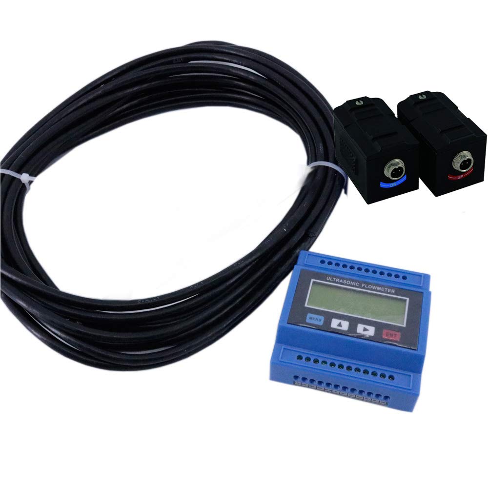
Figure 3: The complete VTSYIQI Ultrasonic Flow Meter system, including the main unit, two clamp-on transducers, and connecting cables.

Figure 4: All components laid out, showing the main unit, transducers, cables, and pipe mounting clamps.
4. Setup and Installation
4.1 Transducer Installation
The TL-1-HT uses clamp-on transducers, which are installed on the outer surface of the pipe. Proper installation is crucial for accurate measurements.
- Select an Appropriate Location: Choose a straight pipe section free from elbows, valves, or pumps for a distance of at least 10 pipe diameters upstream and 5 pipe diameters downstream.
- Prepare the Pipe Surface: Clean the outer surface of the pipe thoroughly to remove any rust, paint, or debris. A smooth surface ensures good acoustic coupling.
- Apply Coupling Gel: Apply a generous amount of ultrasonic coupling gel to the contact surface of both transducers and the pipe surface where they will be mounted.
- Mount Transducers: Position the transducers on the pipe according to the specified mounting method (Z-method, V-method, etc., depending on pipe size and liquid). Ensure they are securely clamped to prevent movement. The distance between transducers is critical and should be calculated based on pipe diameter, material, and liquid type. Refer to the instrument's internal setup menu for precise spacing.
- Connect Cables: Connect the transducer cables to the main unit's designated ports (TX1, RX1, TX2, RX2 if applicable). Ensure connections are secure and waterproof.
4.2 Wiring Diagram and Power Supply
The main unit features multiple terminal blocks for power, signal input/output, and communication. Refer to the images below for terminal identification.

Figure 5: Top view of the main unit showing terminal connections for transducers (TX1, T1, GND, TX2, T2) and signal outputs (A15, A14, A13, OCT1-, OCT1+, RLY-, RLY+).

Figure 6: Bottom view of the main unit showing terminal connections for power (24V+, 24V-), RS485 communication (485+, 485-), analog input (AO-IN), and other inputs (UP+, UP-, DN+, DN-, GND).
Power Connection: Connect the power supply (DC8~36V or AC85~264V) to the designated "24V+" and "24V-" terminals. Ensure correct polarity for DC power.
Signal Output:
- 4-20mA Output: Connect to the 4-20mA output terminals.
- OCT Pulse Output: Connect to the OCT1- and OCT1+ terminals.
- Relay Output: Connect to the RLY- and RLY+ terminals.
Signal Input: The 3-way 4-20mA input can be used for external signals, such as PT100 platinum resistors for heat measurement. Connect these to the A13, A14, A15 terminals as per your application requirements.
RS485 Communication: Connect RS485 communication lines to the "485+" and "485-" terminals for MODBUS communication with external systems.
5. Operating Instructions
5.1 Basic Operation and Menu Navigation
The main unit features a display and four control buttons: MENU, UP (▲), DOWN (▼), and ENT (Enter).
- MENU: Press to enter the main menu or go back to the previous menu level.
- UP (▲) / DOWN (▼): Use to scroll through menu options or adjust parameter values.
- ENT: Press to confirm a selection or enter a submenu.
Upon powering on, the device will typically display the current flow rate. Use the MENU button to access various settings and diagnostic screens.
5.2 Initial Configuration
After installation, configure the flow meter with the correct pipe parameters:
- Pipe Diameter: Enter the outer diameter of the pipe.
- Pipe Material: Select the material of the pipe from the predefined list. This affects the sound speed.
- Liner Material (if applicable): If the pipe has a liner, specify its material and thickness.
- Liquid Type: Select the type of liquid being measured.
- Transducer Spacing: The meter will calculate the optimal transducer spacing based on the entered parameters. Adjust the physical transducer position on the pipe to match this calculated distance.
- Zero Calibration: Perform a zero calibration when there is no flow in the pipe to ensure accurate readings.
Detailed instructions for each menu option are available within the device's firmware. Consult the on-screen prompts for guidance.
6. Maintenance
Regular maintenance ensures the longevity and accuracy of your VTSYIQI Ultrasonic Flow Meter TL-1-HT.
- Clean Transducers: Periodically inspect and clean the transducer surfaces and the pipe contact area. Reapply coupling gel if it has dried out or been disturbed.
- Inspect Cables and Connections: Check all cables for signs of wear or damage. Ensure all electrical connections are secure and free from corrosion.
- Environmental Check: Ensure the main unit is protected from extreme temperatures, direct sunlight, and excessive vibration.
- Recalibration: Depending on application requirements and local regulations, periodic recalibration may be necessary to maintain measurement accuracy.
7. Troubleshooting
This section addresses common issues you might encounter with the flow meter.
| Problem | Possible Cause | Solution |
|---|---|---|
| No flow reading or unstable reading |
|
|
| Inaccurate flow reading |
|
|
| Display is blank |
|
|
If the problem persists after attempting these solutions, contact VTSYIQI customer support for further assistance.
8. Specifications
| Accuracy | ±1% |
| Velocity Range | 0 to ±10m/s, Bi-directional measurement |
| Pipe Size | DN300-6000mm (11.81-236.22 inches) |
| Temperature Range | -30°C to 160°C |
| Liquid Type | Single liquid capable of transmitting ultrasound (e.g., water, seawater, sewage, oil) |
| Pipe Material | Steel, stainless steel, cast iron, copper, PVC, aluminum, glass steel, etc. (Liner allowed) |
| Signal Output | 1 way 4-20mA, 1 way OCT pulse, 1 way Relay output |
| Signal Input | 3 way 4-20mA input (for heat measurement via PT100 platinum resistor) |
| Interface | RS485, supports MODBUS |
| Power Supply | DC8~36V or AC85~264V |
| Package Dimensions | 15.75 x 7.87 x 3.94 inches |
| Weight | 4.41 Pounds |
| Manufacturer | VTSYIQI |
9. Warranty and Support
VTSYIQI products are manufactured to high-quality standards. For specific warranty terms and conditions, please refer to the documentation provided at the time of purchase or contact VTSYIQI customer service.
For technical support, troubleshooting assistance, or service inquiries, please contact your authorized VTSYIQI distributor or visit the official VTSYIQI store online: VTSYIQI Store.


