1. Introduction
This manual provides essential information for the proper handling, installation, and application of the KEMET T591D107M010ATE040 Tantalum Polymer Capacitor. The T591 series offers high capacitance, low ESR, and stable performance across a wide temperature range, making it suitable for various demanding electronic applications.
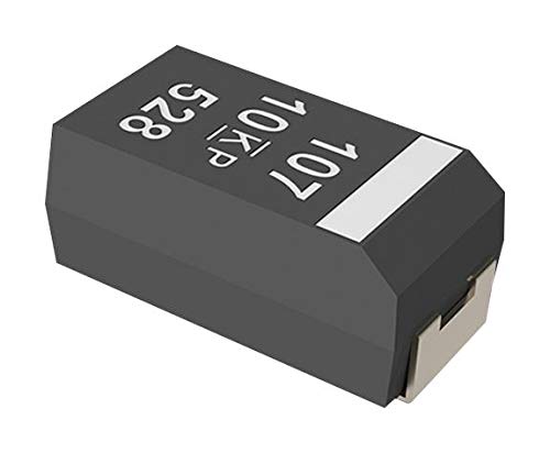
Figure 1: KEMET T591D107M010ATE040 Tantalum Polymer Capacitor. This image shows the compact, rectangular surface-mount component with markings "107", "10KP", and "528" on its top surface, indicating its capacitance, voltage, and manufacturing code. The silver-colored terminals are visible on the ends.
2. Installation and Handling
Proper handling and installation are crucial for the optimal performance and longevity of the capacitor. These components are sensitive to excessive heat and mechanical stress.
2.1. Storage
- Store capacitors in their original packaging in a dry, cool environment, away from direct sunlight and corrosive gases.
- Maintain storage temperature between 5°C and 35°C and relative humidity below 60%.
2.2. Mounting Considerations
- This capacitor is designed for surface mount technology (SMT). Ensure proper pad layout on the Printed Circuit Board (PCB) according to industry standards (e.g., IPC-7351).
- Observe polarity: Tantalum capacitors are polarized. The positive terminal is typically marked with a bar or a plus sign on the capacitor body. Incorrect polarity can lead to component failure.
- Avoid excessive mechanical stress during placement. Use pick-and-place machines with appropriate nozzle pressure.
2.3. Soldering Guidelines
Reflow soldering is the recommended method for mounting. Wave soldering is generally not recommended for polymer capacitors due to thermal stress.
- Reflow Profile: Adhere strictly to the recommended reflow soldering profile provided by KEMET. Exceeding maximum temperature or dwell time can damage the component.
- Peak Temperature: Typically, peak temperature should not exceed 260°C for a maximum of 10 seconds.
- Thermal Shock: Minimize rapid temperature changes during preheating and cooling phases to prevent thermal shock.
- Cleaning: If cleaning is required after soldering, use mild, non-aggressive cleaning agents. Avoid ultrasonic cleaning, which can cause mechanical damage.
3. Operating Conditions and Application Notes
To ensure reliable operation, the capacitor must be used within its specified electrical and environmental limits.
3.1. Voltage Application
- Rated Voltage (VR): Do not apply a continuous voltage exceeding the rated voltage of 10V.
- Surge Voltage (VS): Brief surges up to 13V are permissible, but continuous operation at surge voltage is not allowed.
- Derating: For optimal reliability, especially in high-temperature or high-ripple current applications, apply a voltage derating. KEMET recommends derating by 10% to 20% of the rated voltage.
3.2. Ripple Current
- Ensure that the ripple current applied does not exceed the maximum permissible ripple current specified in the datasheet, considering the operating frequency and temperature. Excessive ripple current can lead to overheating and premature failure.
3.3. Temperature Range
- Operate the capacitor within its specified operating temperature range, typically -55°C to +105°C. Performance characteristics, such as capacitance and ESR, will vary with temperature.
4. Maintenance
KEMET T591 series capacitors are passive components designed for long-term reliability and typically require no routine maintenance once properly installed and operated within specifications. However, periodic inspection of the PCB assembly is recommended.
- Visual Inspection: Periodically inspect the capacitor and surrounding PCB area for any signs of physical damage, discoloration, or solder joint degradation.
- Environmental Control: Ensure the operating environment remains within specified temperature and humidity limits to prevent long-term degradation.
- Dust and Contaminants: Keep the electronic assembly free from excessive dust and conductive contaminants, which can lead to short circuits or performance issues.
5. Troubleshooting
Issues with capacitors are often related to improper application or external circuit conditions. This section outlines common problems and potential causes.
| Problem | Possible Cause | Solution |
|---|---|---|
| Capacitor failure (short circuit/open circuit) |
|
|
| Reduced capacitance or increased ESR |
|
|
| Physical damage (cracks, swelling) |
|
|
For persistent issues, consult the full KEMET T591 series datasheet or contact KEMET technical support.
6. Specifications
Key specifications for the KEMET T591D107M010ATE040 Tantalum Polymer Capacitor are summarized below. Refer to the official KEMET datasheet for complete and detailed specifications.
| Parameter | Value |
|---|---|
| Capacitance | 100 µF |
| Rated Voltage (VR) | 10 V |
| Tolerance | ±20% |
| ESR (Equivalent Series Resistance) | 0.04 ohm (40 mΩ) |
| Series | T591 |
| Case Size | D Case |
| Operating Temperature Range | -55°C to +105°C |
| Manufacturer | KEMET |
7. Support and Further Information
For detailed technical specifications, application notes, and design resources, please visit the official KEMET website or contact their technical support team.
- KEMET Official Website: www.kemet.com
- Product Datasheet: Search for "T591D107M010ATE040" on the KEMET website for the specific datasheet.


